














 ● 20 min read
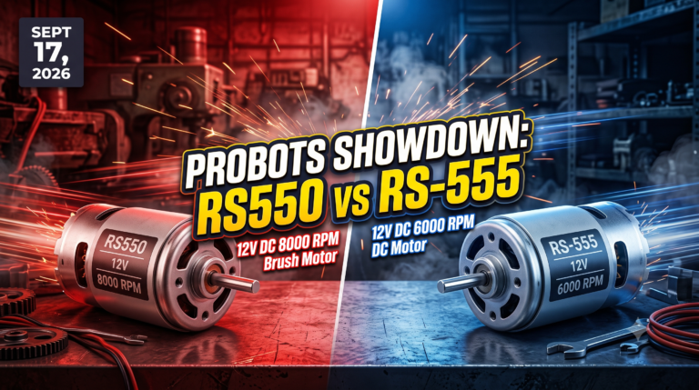
Showdown: RS550 12V DC 8000 vs RS-555 12V DC 6000 RPM DC Motor
Vol. 56 | The Heavyweight DC Drivetrain Duel Reliability isn’t optional when you’re designing actuators that need to move actual steel or
Read Article →
| Bulk Pricing | ||
|---|---|---|
| QTY | Unit Price(Inlc. GST) | |
| 10+ | ₹3,919.02 ₹ 3321.2 + 597.82 GST | |
| 20+ | ₹3,879.03 ₹ 3287.31 + 591.72 GST | |
| 30+ | ₹3,839.04 ₹ 3253.42 + 585.62 GST | |
| 50+ | ₹3,759.06 ₹ 3185.64 + 573.42 GST | |
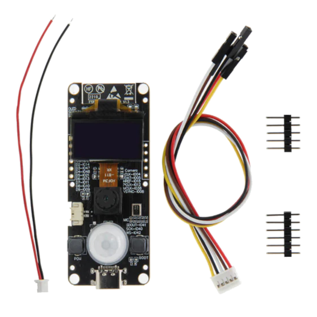
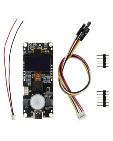
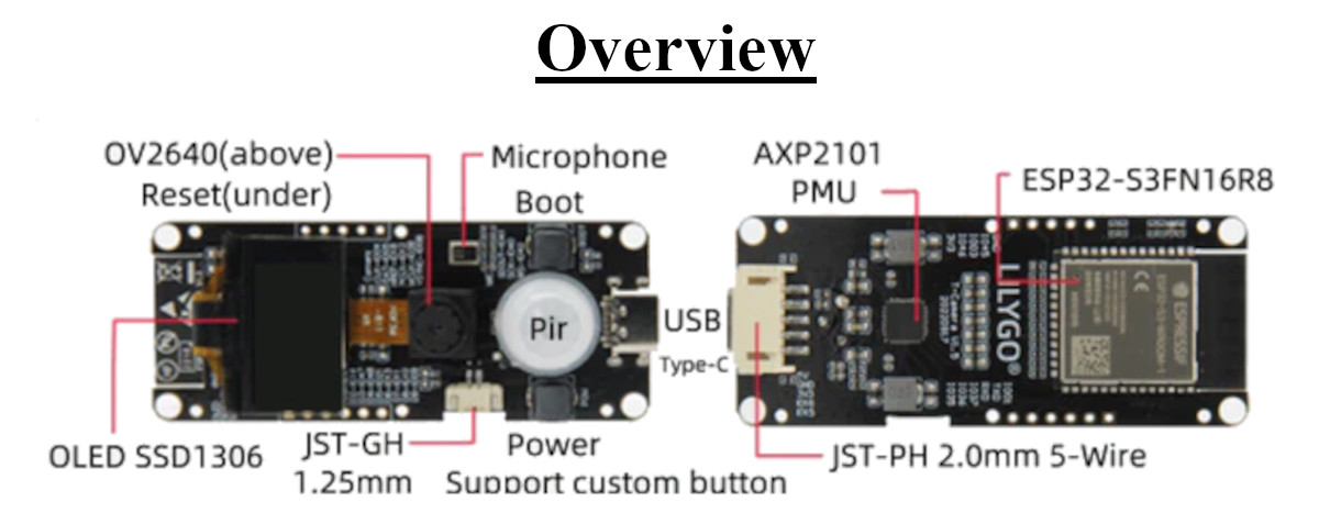
Create powerful AI vision projects! The LILYGO T-Camera S3 features an ESP32-S3 processor (16MB Flash/8MB PSRAM), a 2MP OV2640 camera, a PIR motion sensor, an I2S microphone, and an OLED display in one compact board.
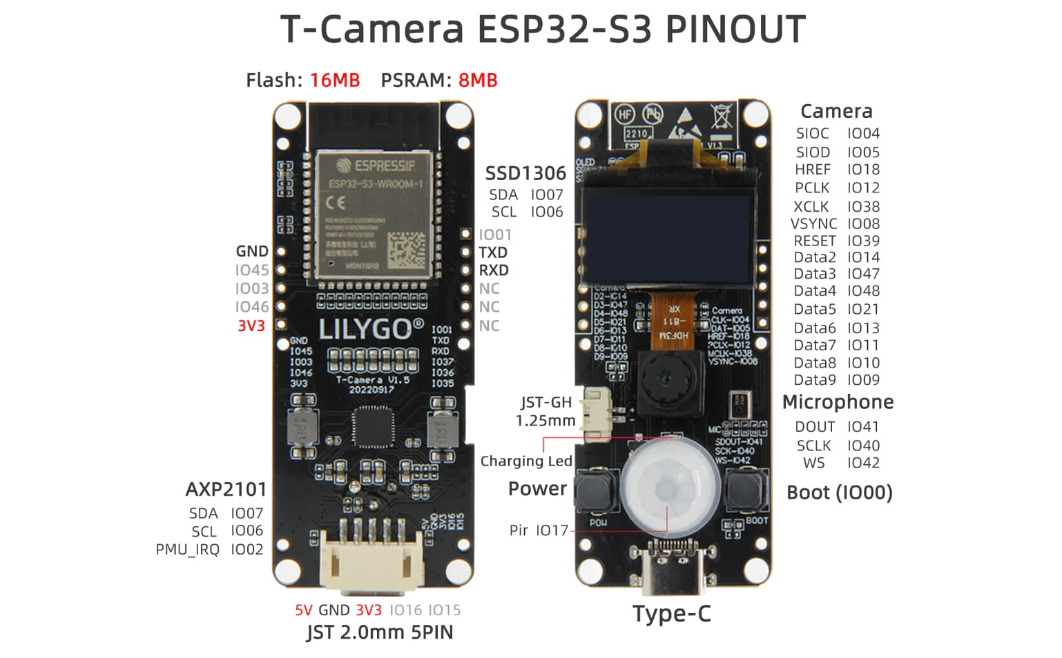
AI Vision and Audio Processing The T-Camera S3 is built around the Espressif ESP32-S3 module, which features vector instructions specifically optimized for accelerating neural network and machine learning workloads. With 16MB of Flash and 8MB of PSRAM, it easily handles high-resolution image buffering from the integrated 2-Megapixel OV2640 camera. Furthermore, it includes a digital I2S microphone (wired to IO41, IO40, IO42), allowing your project to not only see but also listen, making it perfect for wake-word detection or acoustic event monitoring.
Hardware-Level Motion Detection Why keep the camera running and wasting power when nothing is happening? The board features a prominent white PIR (Passive Infrared) sensor dome directly below the camera. This hardware sensor detects the infrared heat signatures of humans or animals moving across its field of view. Wired to IO17, you can program the ESP32-S3 to remain in a deep sleep state until the PIR sensor is triggered, allowing the board to run on battery power for extended periods.
Self-Contained Interface & Power For debugging and local feedback, the board integrates a classic SSD1306 OLED display. You can use this to display the current IP address, motion status, or even a low-framerate viewfinder. Power delivery is expertly handled by the advanced AXP2101 Power Management Unit (PMU). This chip safely regulates USB power, manages LiPo battery charging via the JST-GH 1.25mm connector, and allows programmatic control over the power rails for the camera and peripherals.
Specifications
Microcontroller: ESP32-S3-WROOM-1 (Dual-core, up to 240 MHz)
Flash Memory: 16MB
PSRAM: 8MB
Camera Module: OV2640 (2 Megapixel)
Display: SSD1306 I2C OLED
Motion Sensor: PIR (Passive Infrared) Sensor
Audio: Digital I2S Microphone
Power Management: AXP2101 PMU
Wireless: Wi-Fi (802.11 b/g/n) & Bluetooth 5 (LE)
Interfaces: USB Type-C, JST-GH 1.25mm (Battery), JST 2.0mm 5-Pin (Expansion)
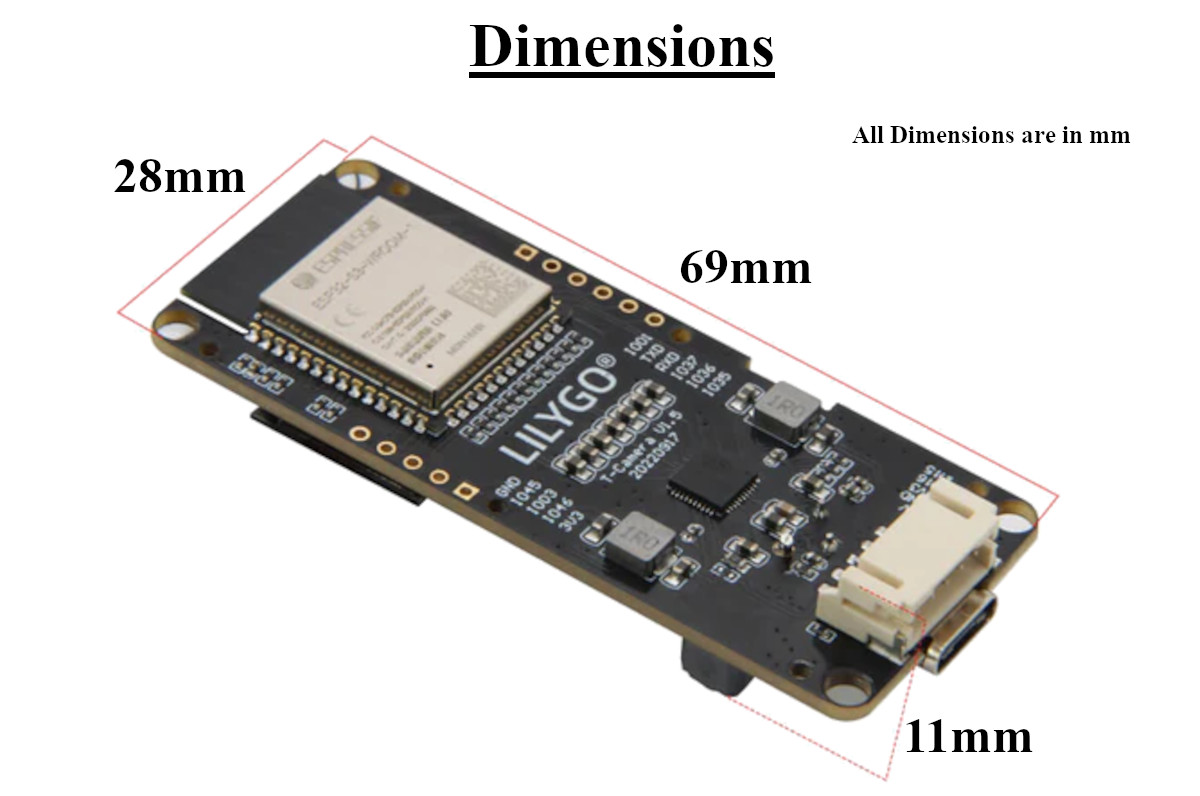
Dimensions: 69mm (L) x 28mm (W) x 11mm (H)
Key Applications and Projects
DIY Smart Doorbell: Using the PIR sensor to detect a visitor, snapping a photo with the OV2640, and pushing the image to a Telegram bot via Wi-Fi.
Wildlife Trap Camera: Placing the board in a weatherproof enclosure in the woods, running off a battery, and logging photos of passing animals to a remote server.
Machine Learning Nodes: Utilizing the ESP-WHO framework for localized face recognition or object detection without needing a cloud connection.
Unlock New Capabilities (Project Evolution) The AI Desk Assistant: Evolve this hardware beyond a simple security camera! Mount the T-Camera S3 on a 3D-printed stand on your desk. Train a lightweight TensorFlow Lite model to recognize specific hand gestures. You can program the board to watch you via the OV2640; when you hold up a "peace sign," the ESP32-S3 recognizes the gesture and sends an HTTP request to Home Assistant to turn on your studio lights. Use the OLED screen to display a friendly pair of digital eyes that blink and react when the PIR sensor detects you sitting down at your desk!
1 x LILYGO T-Camera S3 Board (with OV2640, PIR, OLED)
1 x JST 1.25mm Battery Pigtail Cable
1 x JST 2.0mm 5-Pin Expansion Cable
2 x Male Header Pins (Unsoldered)
Downloads & Links
1. What microcontroller drives this board? It is powered by the Espressif ESP32-S3-WROOM-1 module, which is highly optimized for AI and machine learning tasks.
2. What are the specifications of the camera? It uses the popular OV2640 camera module, which supports a maximum resolution of 2 Megapixels (1600x1200) and JPEG output formats.
3. Does this board have PSRAM for image buffering? Yes, it features 8MB of PSRAM, which is absolutely critical for capturing and processing high-resolution images smoothly.
4. How does the PIR sensor work? The PIR (Passive Infrared) sensor detects changes in infrared radiation caused by moving warm bodies (like humans or pets). It is wired to IO17 and acts as a digital trigger (HIGH/LOW) when motion is detected.
5. Can I use the microphone for audio recording? Yes. The board features a digital I2S microphone (wired to DOUT IO41, SCLK IO40, WS IO42). You can use this for recording audio clips, measuring ambient noise levels, or wake-word detection.
6. What is the AXP2101 chip used for? The AXP2101 is a highly advanced Power Management Unit (PMU). It safely charges the LiPo battery and allows your software to individually turn power rails to the camera, screen, and sensors on or off to save battery.
7. Crucial: Why is my camera or screen not working out of the box? Because power is routed through the AXP2101 PMU, you must initialize the PMU in your code and command it to turn on the power rails for the camera and OLED. If you skip this step, the peripherals will remain unpowered and throw initialization errors.
8. What are the pins for the OLED display? The SSD1306 OLED uses the I2C bus, mapped to SDA (IO07) and SCL (IO06). Note that these are the exact same I2C pins used to communicate with the AXP2101 PMU.
9. How do I connect a battery? There is a JST-GH 1.25mm connector located between the PIR sensor and the USB port. A matching cable is included. Ensure your battery polarity matches the board markings.
10. What is the 5-pin port on the bottom for? This is a JST 2.0mm 5-PIN expansion port breaking out 5V, GND, 3V3, IO16, and IO15. It is highly useful for attaching external servos, relays, or serial sensors. A cable is included.
11. How do I put the board into bootloader mode manually? Hold down the "Boot" button, press and release the Reset button (located under the edge of the screen/camera module), and then release the "Boot" button.
12. Does it support Wi-Fi and Bluetooth? Yes, the ESP32-S3 features native 2.4 GHz Wi-Fi (802.11 b/g/n) and Bluetooth 5 (LE).
13. What settings should I use in the Arduino IDE? Select the "ESP32S3 Dev Module". Ensure you set "USB CDC On Boot" to Enabled, Flash Size to 16MB, and PSRAM to "OPI PSRAM".
14. Can I use the ESP32-CAM example sketch in Arduino? Yes, but you must select the custom camera pin definitions matching this specific board, and you must add the AXP2101 initialization code to the setup() block before calling esp_camera_init().
15. Is there a MicroSD card slot on this board? No. Due to the high integration of the camera, screen, PMU, mic, and PIR sensor, there is no physical space for an SD card slot. Images should be processed locally or sent over Wi-Fi.
16. What are the exact dimensions? The board measures 69mm in length, 28mm in width, and 11mm in thickness (measured from the PCB to the top of the PIR dome).
17. Why is the camera ribbon cable folded like that? The OV2640 module sits directly on top of the OLED display, so the flexible Kapton ribbon cable is folded backwards to connect to the FPC socket on the PCB beneath it. Be very careful not to crease or tear this cable.
18. Can I stream video from this board? Yes. You can run a web server on the ESP32-S3 that streams a MJPEG video feed to a web browser on your local network.
19. What logic voltage do the GPIO pins use? Like all ESP32 chips, the GPIO pins operate strictly on 3.3V logic.
20. Can I replace the camera lens? The standard OV2640 module usually comes with a fixed lens glued into the housing. While technically possible to swap if you buy a different OV2640 module, it is generally intended to be used as-is.
| Core Chipset: | ESP32-S3 |
|---|---|
| Flash Memory: | 16 MB |
| PSRAM: | 8 MB |
| Wireless Connectivity: | WiFi, Bluetooth |
| Antenna Type: | Onboard PCB |
Probots sells every Electronics Part for your next Project. You can order 10,000+ Electronic Parts Online - Arduino, Raspberry Pi, NodeMCU Development Boards, Sensors, Motors, Motor Drivers, SMPS, Plastic Enclosures etc in India directly on probots.co.in
We delivery electronics components and parts throughout India using standard couriers like Bluedart, Delhivery & India Post.
For order related queries contact -
This item is covered by a warranty of 7 days from the date of delivery, against confirmed manufacturing defects only, as verified by Probots' own testing and investigation. In case of a confirmed defect, we will replace the item — a refund is issued only if a replacement can't be supplied (e.g. discontinued or out of stock). Transit damage or a wrong item received must be reported within 3 days of delivery.
If the product shows signs of misuse, tampering, physical damage, static discharge, liquid or fire damage, use of unapproved chemicals, or has been soldered or physically altered in any way.
China
Probots sells every Electronics Part for your next Project. You can order 10,000+ Electronic Parts Online - Arduino, Raspberry Pi, NodeMCU Development Boards, Sensors, Motors, Motor Drivers, SMPS, Plastic Enclosures etc in India directly on probots.co.in
We offer specialized services for Bulk, Wholesale & B2B Customers like discounted prices, additional shipping options, customised products, etc . Customer with large quantity & regular orders qualify for the specialised discounted rates.
We also offer dedicated sales team to assist you with the order process by providing sales quotations, PI, technical support for choosing products, etc.
Note: Business Orders are processed manually and usually take 1-3 days to process compared to placing the order directly on our website. Please plan your purchases accordingly.
Need Help?
For bulk enquiries contact us by -

Probots Electronics is highly regarded for its highly skilled team and knowledgeable staff who provide expert guidance to ensure customers select the right components for their technical projects. The business maintains a strong reputation for prompt service and reliable support, with many clients praising their quick response times and genuine commitment to customer satisfaction.


A very great place for electronics Such a well maintained shop... Felt good shopping here


Nice

For new developments kit available and they will support till working, and I suggest this place strongly


This place has all the electronic parts students will ever need, staff is friendly and the place is organised.


It was a really nice experience! I was happy to find such a wide range of robotics kits for kids, suitable for different age groups and learning levels.

Excellent experience




Good stuff

Buyed them. But no bargain. Helpful staff.


Available all children school project spears parts like electronics


It was good experience




Staff is very patient and helpful

One of the best place for electronics you will get everything you want! With the best and orginal quality

Very helpful staff and the best place to buy components for projects

Wonderful store with expert service and technically strong people.

Prompt delivery, excellent technical support


Large inventory of electronic components and parts. Well trained service personnel and technicians who can quickly identify and rectify product defect if any. They are a reliable and trustworthy online stores.

A very great place for electronics Such a well maintained shop... Felt good shopping here
Nice
For new developments kit available and they will support till working, and I suggest this place strongly
This place has all the electronic parts students will ever need, staff is friendly and the place is organised.
It was a really nice experience! I was happy to find such a wide range of robotics kits for kids, suitable for different age groups and learning levels.
Excellent experience
Good stuff
Buyed them. But no bargain. Helpful staff.
Available all children school project spears parts like electronics
It was good experience
Staff is very patient and helpful
One of the best place for electronics you will get everything you want! With the best and orginal quality
Very helpful staff and the best place to buy components for projects
Wonderful store with expert service and technically strong people.
Prompt delivery, excellent technical support
Large inventory of electronic components and parts. Well trained service personnel and technicians who can quickly identify and rectify product defect if any. They are a reliable and trustworthy online stores.
● 20 min readVol. 56 | The Heavyweight DC Drivetrain Duel Reliability isn’t optional when you’re designing actuators that need to move actual steel or
Read Article → ● 13 min read
Workbench Vol. 49 🚀 The Project Trifecta: 3 Builds to Start Today We don’t just stock parts; we curate ecosystems. This week’s arrivals are desi
Read Article → ● 18 min read
Vol. 59 | The Battle of the Bite-Sized Boards Picture a project that needs full Linux, networking, and GPIO—but has almost no room for a conventional
Read Article →