













 ● 20 min read
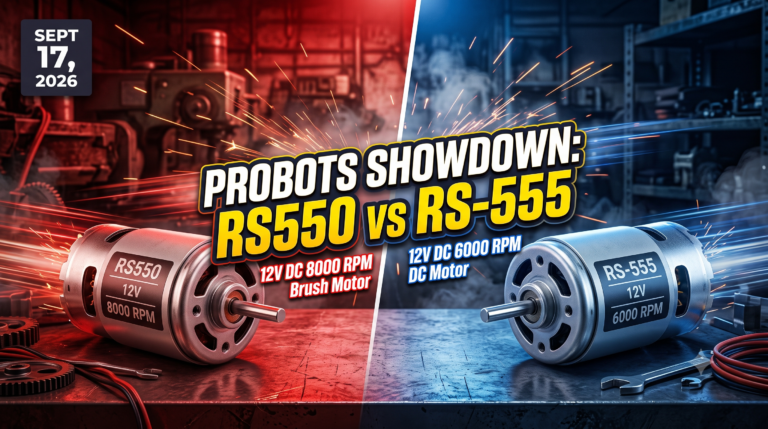
Showdown: RS550 12V DC 8000 vs RS-555 12V DC 6000 RPM DC Motor
Vol. 56 | The Heavyweight DC Drivetrain Duel Reliability isn’t optional when you’re designing actuators that need to move actual steel or
Read Article →
| Bulk Pricing | ||
|---|---|---|
| QTY | Unit Price(Inlc. GST) | |
| 25+ | ₹293.02 ₹ 248.32 + 44.7 GST | |
| 50+ | ₹290.03 ₹ 245.79 + 44.24 GST | |
| 75+ | ₹287.04 ₹ 243.25 + 43.79 GST | |
| 100+ | ₹281.06 ₹ 238.19 + 42.87 GST | |
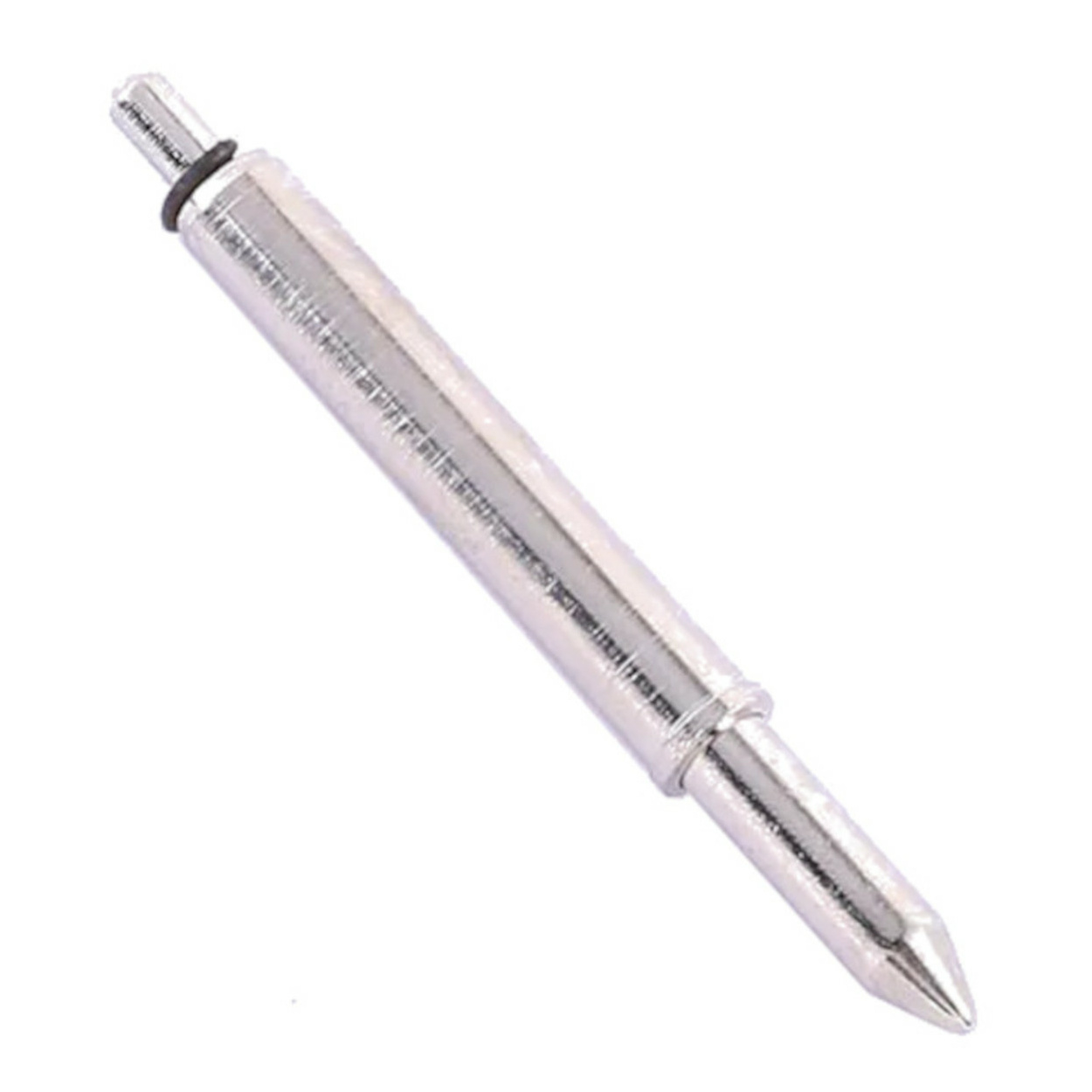
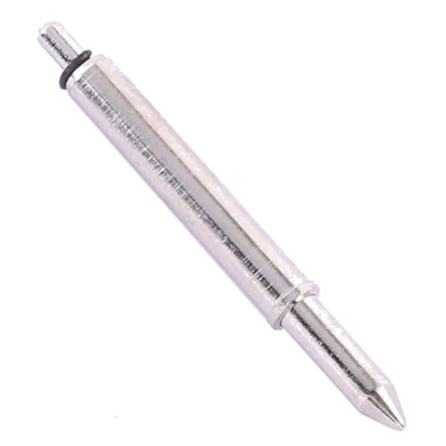
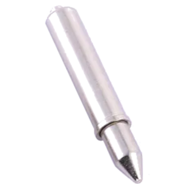
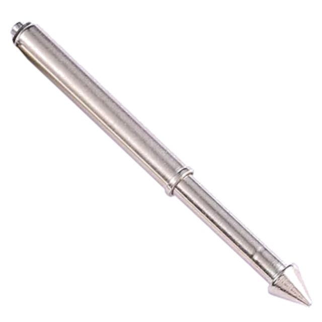
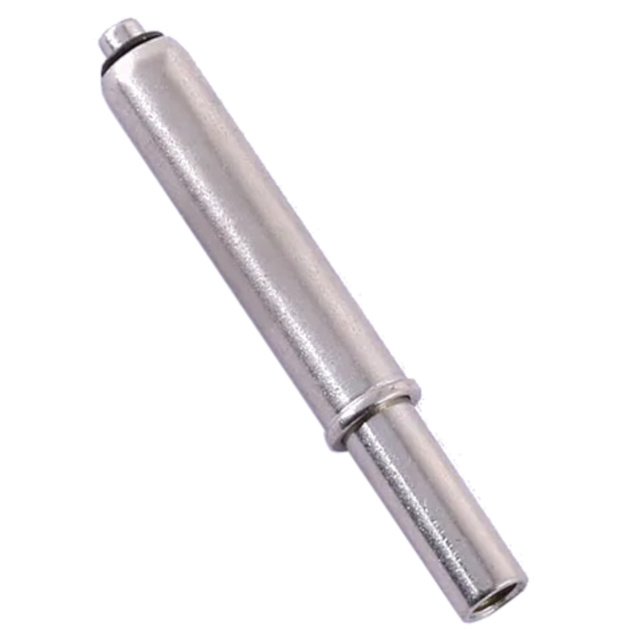
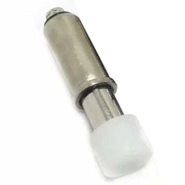
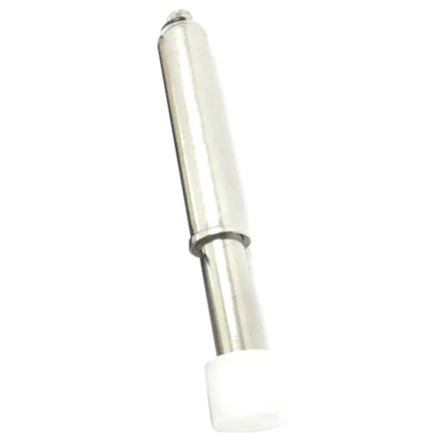
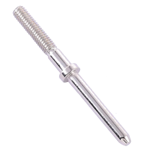
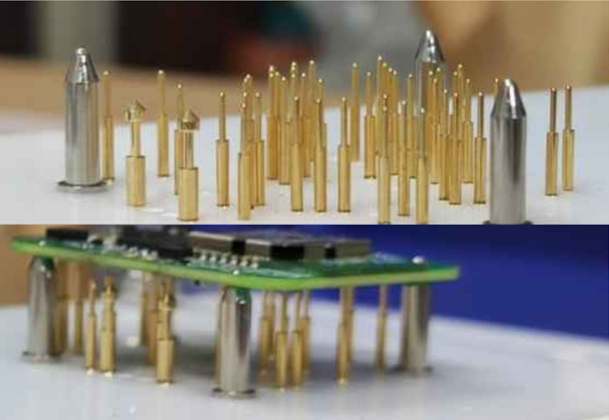
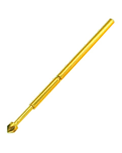
Ensure flawless PCB alignment in your test fixtures! The GP-1S guide pin features a 3.2mm barrel, 300g spring force, and a precise 2.48mm tapered tip to safely align circuit boards before pogo-pin contact.
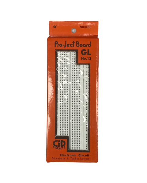
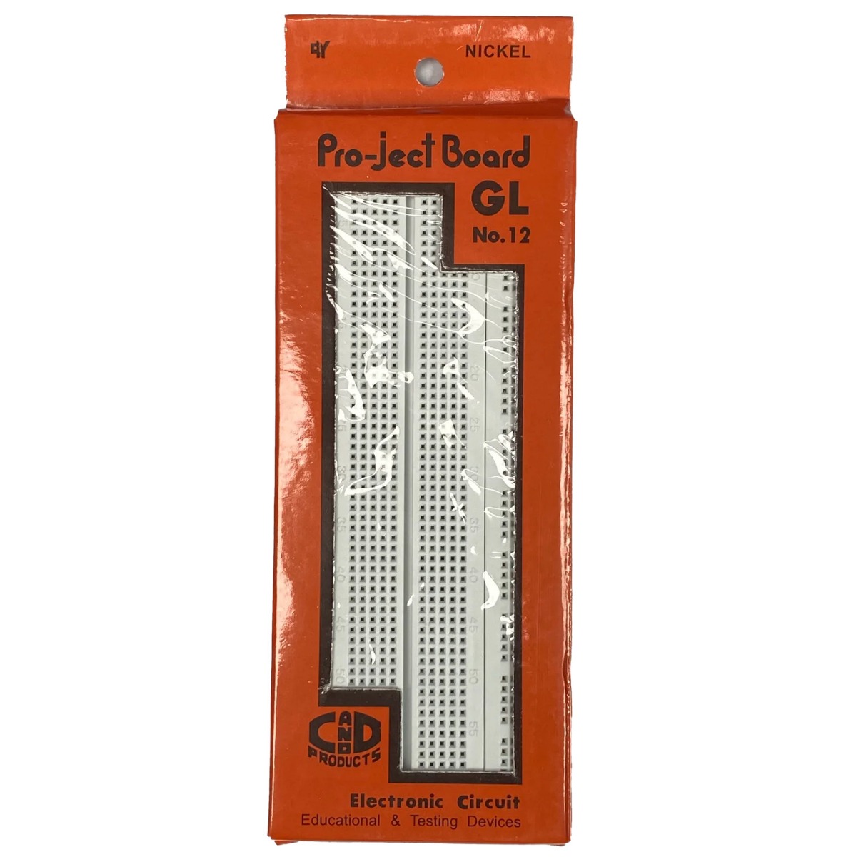 GL-12 840 Points Solderless Breadboard for Electronics Prototyping & DIY Projects ₹86.00
 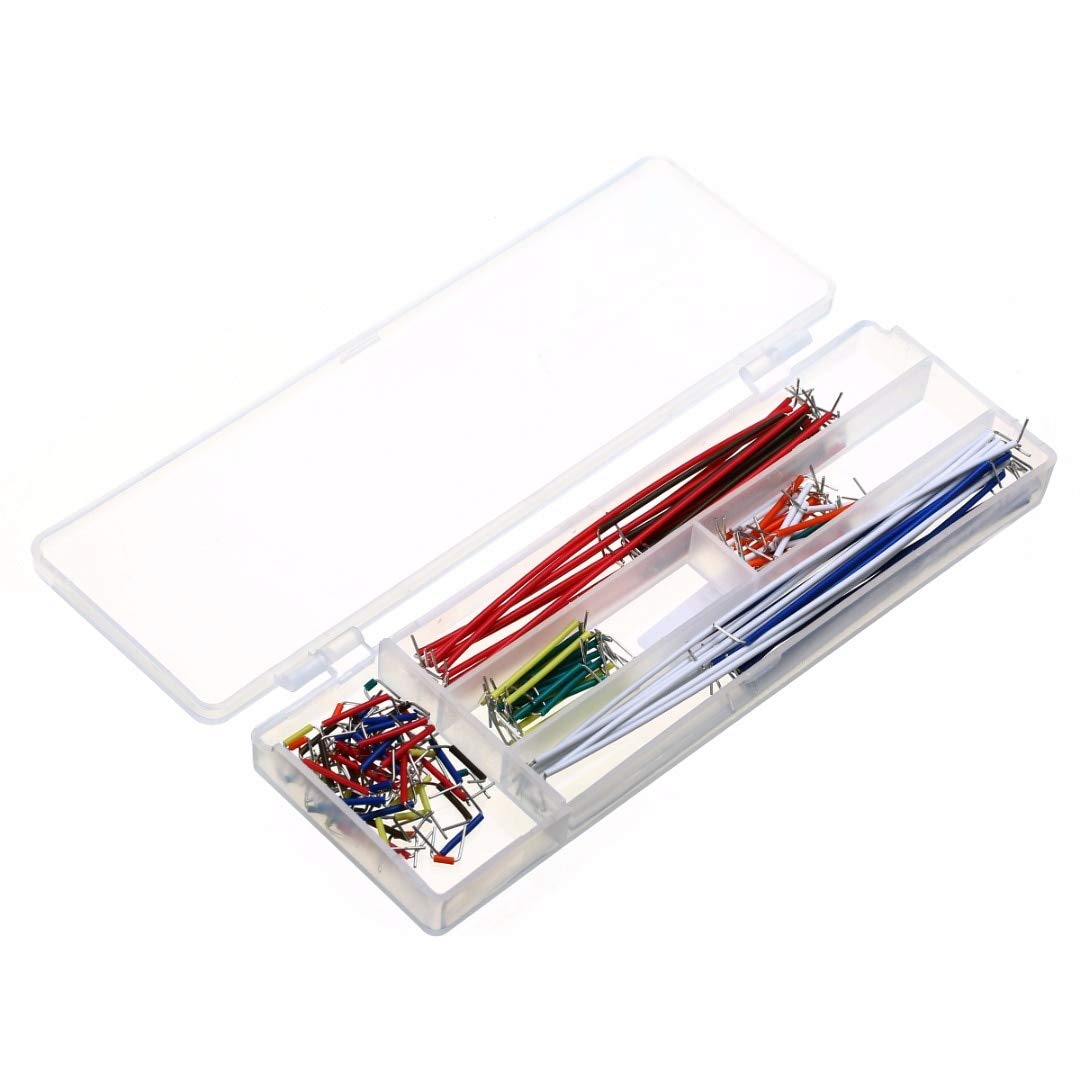 BreadBoard Jumper Kit 140pcs Solderless Cable Wire for Prototyping ₹149.00
 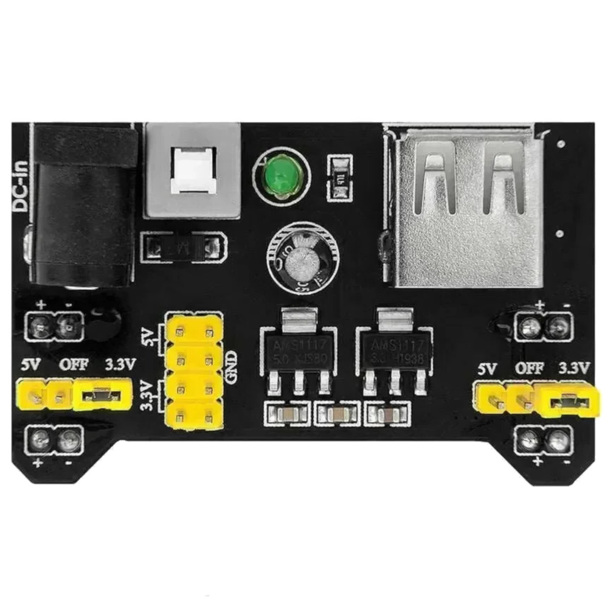 MB102 Breadboard Power Supply Module - 3.3V / 5V Dual Rail Regulator ₹69.00
 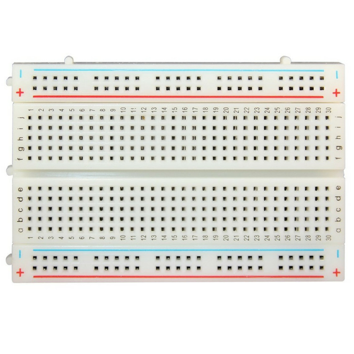 Breadboard for Electronics Solderless Prototyping 400 Points ₹49.00
 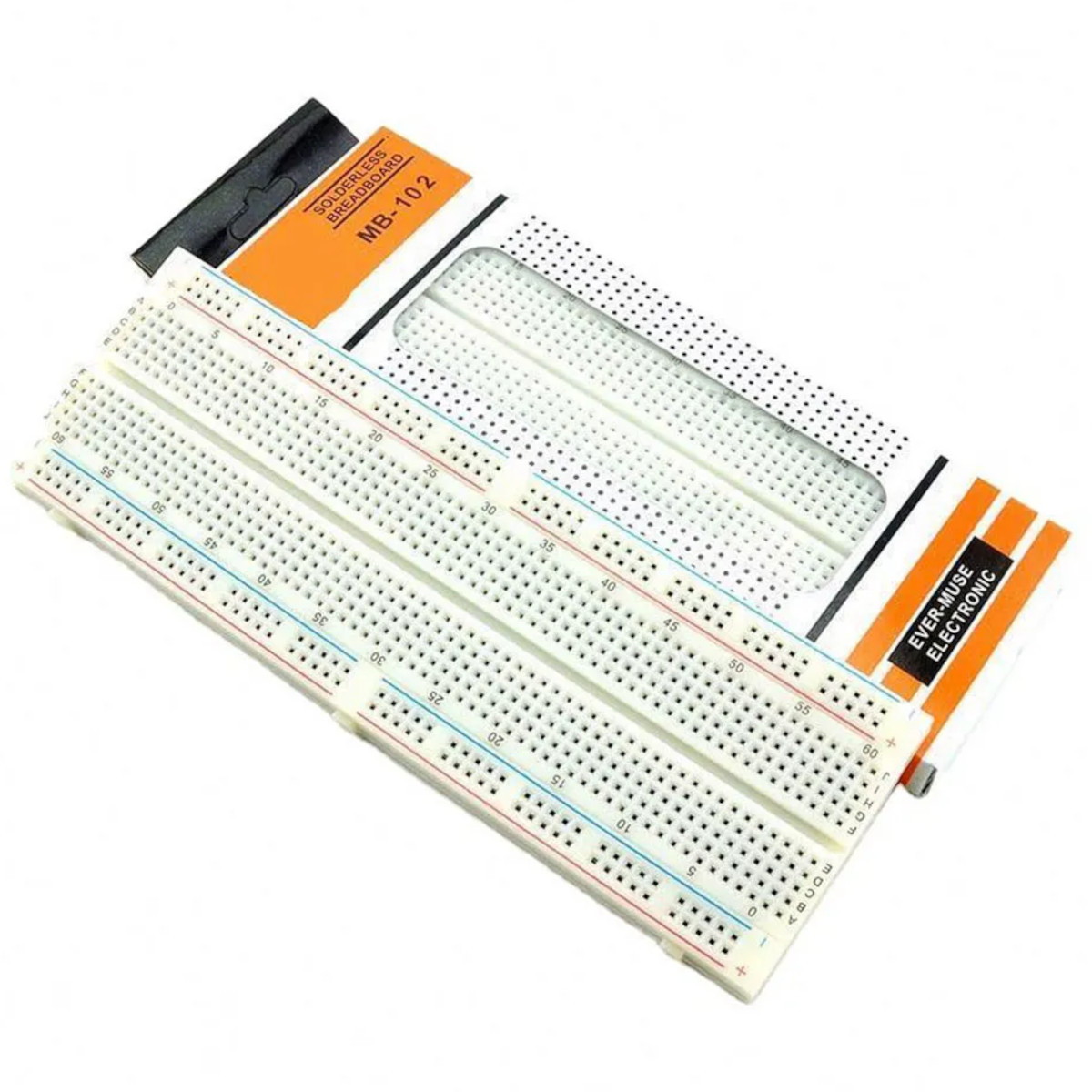 MB102 830 Points Solderless Prototype Breadboard - 2.54mm Pitch, Power Rails ₹100.00
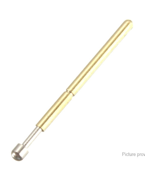
 The First Point of Contact When building a testing jig, you are often dealing with dozens of tiny spring-loaded pogo pins that must hit 1mm copper test pads simultaneously. If the PCB is shifted even slightly, the pogo pins will miss the pads, potentially shorting out components. The GP-1S is designed to be the "First Point of Contact." The exposed pin sits higher than your electrical pogo pins. Its bullet-nosed tapered tip catches the large, standardized mounting holes (tooling holes) on your PCB, naturally sliding the board into the exact X and Y coordinates required before the electrical testing pins even touch the board.
Spring-Loaded Safety Mechanism In automated assembly lines or rapid manual testing, human error occurs. A worker might place a board backward, or place a PCB that lacks the correct tooling holes. If you use rigid, solid metal dowels for alignment, closing the heavy toggle clamp of your testing jig will instantly snap and destroy the fiberglass PCB. The GP-1S prevents this. It utilizes a heavy-duty internal spring calibrated to 300g of force. This is strong enough to easily guide the board laterally, but if a solid, flat section of the PCB is forced down on top of the pin, the pin simply retracts into its barrel, saving the board from catastrophic damage.
Simple Press-Fit Installation Mounting these pins is straightforward. The main body barrel measures exactly 3.2mm in diameter. By drilling a matching high-tolerance hole into your acrylic or Bakelite fixture base, you can press-fit the pin securely into place. A highly precise 3.5mm flanged collar acts as a hard stop, ensuring the pin sits at the exact perfect height every single time and cannot fall through the bottom of your fixture.
Note: Variations in panel hole size, thickness, material, and installation methods will affect the loads. Values may not be consistent with loading in an assembly. Strongly recommended for testing in the application
Specifications
Model Name: GP-1S
Function: Mechanical Alignment / Positioning
Barrel Outer Diameter (OD): 3.2mm
Flange / Collar Diameter: 3.5mm
Tip Diameter: 2.48mm
Total Exposed Pin Length: 8.5mm (6.0mm straight + 2.5mm taper)
Barrel Length: 18.0mm
Spring Force: ~300g (3.0N)
Material: Nickel/Gold Plated Brass and Stainless Steel
Mounting Method: Press-Fit (Self-Clinching)
Key Applications and Projects
ICT / FCT Test Jigs: Building "Bed of Nails" In-Circuit Testing and Functional Circuit Testing fixtures for mass-producing custom electronics.
Microcontroller Programming Docks: Creating a rapid-flashing dock for ESP32 or Arduino modules where you simply press the board down to upload firmware without soldering headers.
Automated CNC Alignment: Using the spring-loaded pins to register blank aluminum or FR4 plates onto a CNC spoilboard before routing.
Unlock New Capabilities (Project Evolution) The Rapid Deployment Flashing Jig: Are you currently hand-soldering jumper wires to flash bootloaders onto your custom PCBs? Stop wasting hours of production time! Evolve your workflow by building a rapid programming jig. Cut a piece of thick clear cast acrylic. Drill two 3.2mm holes in opposite corners for these GP-1S guide pins. Drill smaller holes for standard P100-E2 pogo pins aligned to your PCB's programming pads. Mount a vertical toggle clamp to the acrylic. Now, you can simply drop your blank PCB onto the guide pins, pull the clamp down, flash the firmware in 5 seconds, and release! You have just stepped up to professional, factory-level production!
1 x GP-1S Spring-Loaded Guide Pin (3.2mm OD)

1. What is the main purpose of the GP-1S guide pin? It is a purely mechanical alignment pillar. It guides a printed circuit board (PCB) into the exact perfect position on a testing fixture so that electrical pogo pins can accurately hit the board's test pads.
2. How does this differ from a standard pogo pin? Standard pogo pins (like the P100 series) are thin, fragile, and designed to transmit electrical signals. The GP-1S is much thicker, highly rigid, and carries no electrical signal; its only job is physical structural alignment.
3. Why is the pin spring-loaded instead of solid metal? If a board is inserted incorrectly or lacks a tooling hole, pressing down on a solid metal dowel will crack the PCB. A spring-loaded pin will safely retract into its barrel under pressure, protecting the delicate circuit board.
4. What is the exact outer diameter of the main barrel? The main cylindrical body (barrel) that mounts into your fixture is exactly 3.2mm in diameter.
5. What size hole should I drill to mount this? For a tight friction-fit in acrylic or Bakelite, a drill bit exactly matching 3.2mm (or extremely close, like 3.15mm depending on material shrinkage) is recommended so it securely presses in without needing glue.
6. What is the diameter of the upper positioning pin? The upper pin that actually passes through the hole in your PCB is 2.48mm in diameter. Your PCB tooling holes must be larger than 2.5mm for this pin to fit.
7. How long is the exposed pin section? The exposed section protruding above the collar is 8.5mm total (comprising a 6.0mm straight section and a 2.5mm tapered tip).
8. What is the length of the main barrel? The main 3.2mm diameter barrel measures 18mm in length.
9. How do I stop the pin from falling entirely through my mounting hole? The pin features a slightly wider flanged collar measuring 3.5mm in diameter. This collar acts as a physical stop, resting flat against the surface of your acrylic base plate.
10. What is the rated spring force? This specific pin features a heavy-duty spring calibrated to approximately 300g (3.0 Newtons) of compression force.
11. Can this be used to transmit power or data? No. While it is made of conductive metal, it is not designed to be wired into a circuit. It is exclusively for mechanical positioning.
12. Is the tip sharp enough to scratch my PCB? No, the tip is bullet-nosed and smoothly tapered. As long as it is aligning with a drilled tooling hole, it will gently slide the board into place without scratching the solder mask.
13. What materials are typically used for the jig's base plate? Fixture bases are usually CNC-routed or laser-cut from 8mm to 10mm thick clear cast Acrylic, Delrin, or FR4 Bakelite sheets.
14. How many guide pins do I need for a single test fixture? You need a minimum of two guide pins per fixture, usually placed at opposite diagonal corners of the PCB, to lock the board's X, Y, and rotational axes perfectly in place.
15. Can I use this for aligning 3D printed parts instead of PCBs? Absolutely. As long as the mating part has a 2.5mm or larger alignment hole, these pins work brilliantly for positioning any flat mechanical assembly.
16. Does this require a separate receptacle socket? No. Unlike electrical pogo pins that slide into brass receptacles for easy swapping, the heavy-duty 3.2mm barrel of the GP-1S is designed to be press-fit directly into the fixture base material.
17. What happens if my PCB tooling hole is smaller than 2.48mm? The guide pin will not be able to pass through the hole. You will need to either design your future PCBs with larger tooling holes or purchase a smaller micro-guide pin.
18. Can this pin withstand high temperatures? It is constructed entirely of metal and can withstand ambient operating temperatures, but it is not intended to be run through reflow ovens or wave soldering machines.
19. How long will the internal spring last? The high-quality internal steel spring is rated for hundreds of thousands of compression cycles in a standard factory environment before showing signs of fatigue.
20. Do I need to lubricate the pin? No, the pin comes factory-assembled and should not be lubricated. Adding oils or grease will attract factory dust and fiberglass shavings, which can eventually jam the internal spring mechanism.
Probots sells every Electronics Part for your next Project. You can order 10,000+ Electronic Parts Online - Arduino, Raspberry Pi, NodeMCU Development Boards, Sensors, Motors, Motor Drivers, SMPS, Plastic Enclosures etc in India directly on probots.co.in
We delivery electronics components and parts throughout India using standard couriers like Bluedart, Delhivery & India Post.
For order related queries contact -
This item is covered by a warranty of 7 days from the date of delivery, against confirmed manufacturing defects only, as verified by Probots' own testing and investigation. In case of a confirmed defect, we will replace the item — a refund is issued only if a replacement can't be supplied (e.g. discontinued or out of stock). Transit damage or a wrong item received must be reported within 3 days of delivery.
If the product shows signs of misuse, tampering, physical damage, static discharge, liquid or fire damage, use of unapproved chemicals, or has been soldered or physically altered in any way.
China
Probots sells every Electronics Part for your next Project. You can order 10,000+ Electronic Parts Online - Arduino, Raspberry Pi, NodeMCU Development Boards, Sensors, Motors, Motor Drivers, SMPS, Plastic Enclosures etc in India directly on probots.co.in
We offer specialized services for Bulk, Wholesale & B2B Customers like discounted prices, additional shipping options, customised products, etc . Customer with large quantity & regular orders qualify for the specialised discounted rates.
We also offer dedicated sales team to assist you with the order process by providing sales quotations, PI, technical support for choosing products, etc.
Note: Business Orders are processed manually and usually take 1-3 days to process compared to placing the order directly on our website. Please plan your purchases accordingly.
Need Help?
For bulk enquiries contact us by -


Probots Electronics is highly regarded for its highly skilled team and knowledgeable staff who provide expert guidance to ensure customers select the right components for their technical projects. The business maintains a strong reputation for prompt service and reliable support, with many clients praising their quick response times and genuine commitment to customer satisfaction.


A very great place for electronics Such a well maintained shop... Felt good shopping here


Nice

For new developments kit available and they will support till working, and I suggest this place strongly


This place has all the electronic parts students will ever need, staff is friendly and the place is organised.


It was a really nice experience! I was happy to find such a wide range of robotics kits for kids, suitable for different age groups and learning levels.

Excellent experience




Good stuff

Buyed them. But no bargain. Helpful staff.


Available all children school project spears parts like electronics


It was good experience




Staff is very patient and helpful

One of the best place for electronics you will get everything you want! With the best and orginal quality

Very helpful staff and the best place to buy components for projects

Wonderful store with expert service and technically strong people.

Prompt delivery, excellent technical support


Large inventory of electronic components and parts. Well trained service personnel and technicians who can quickly identify and rectify product defect if any. They are a reliable and trustworthy online stores.

A very great place for electronics Such a well maintained shop... Felt good shopping here
Nice
For new developments kit available and they will support till working, and I suggest this place strongly
This place has all the electronic parts students will ever need, staff is friendly and the place is organised.
It was a really nice experience! I was happy to find such a wide range of robotics kits for kids, suitable for different age groups and learning levels.
Excellent experience
Good stuff
Buyed them. But no bargain. Helpful staff.
Available all children school project spears parts like electronics
It was good experience
Staff is very patient and helpful
One of the best place for electronics you will get everything you want! With the best and orginal quality
Very helpful staff and the best place to buy components for projects
Wonderful store with expert service and technically strong people.
Prompt delivery, excellent technical support
Large inventory of electronic components and parts. Well trained service personnel and technicians who can quickly identify and rectify product defect if any. They are a reliable and trustworthy online stores.
● 20 min readVol. 56 | The Heavyweight DC Drivetrain Duel Reliability isn’t optional when you’re designing actuators that need to move actual steel or
Read Article → ● 13 min read
Workbench Vol. 49 🚀 The Project Trifecta: 3 Builds to Start Today We don’t just stock parts; we curate ecosystems. This week’s arrivals are desi
Read Article →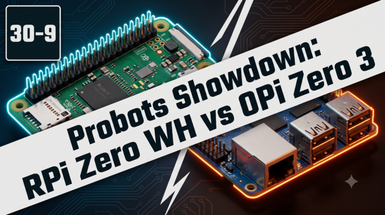 ● 18 min read
Vol. 59 | The Battle of the Bite-Sized Boards Picture a project that needs full Linux, networking, and GPIO—but has almost no room for a conventional
Read Article →