














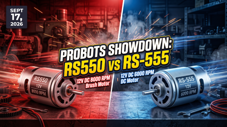
 ● 20 min read
Showdown: RS550 12V DC 8000 vs RS-555 12V DC 6000 RPM DC Motor
Vol. 56 | The Heavyweight DC Drivetrain Duel Reliability isn’t optional when you’re designing actuators that need to move actual steel or
Read Article →
| Bulk Pricing | ||
|---|---|---|
| QTY | Unit Price(Inlc. GST) | |
| 25+ | ₹195.02 ₹ 165.27 + 29.75 GST | |
| 50+ | ₹193.03 ₹ 163.58 + 29.44 GST | |
| 75+ | ₹191.04 ₹ 161.9 + 29.14 GST | |
| 100+ | ₹189.05 ₹ 160.21 + 28.84 GST | |
Safely detect 220V AC mains power with your Arduino or PLC! This 1-channel optocoupler isolates high voltage from your delicate logic board, outputting a clean 3V-24V DC digital signal when AC power is detected.
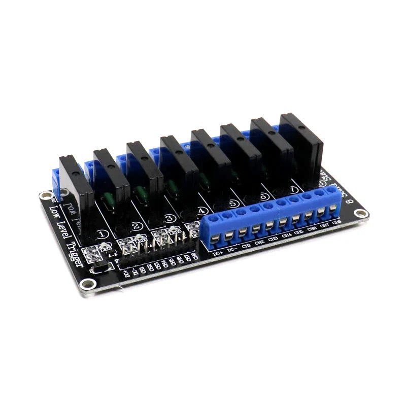 Solid State Relay Module G3MB-202P SSR 5V, 8-Channel ₹959.00
 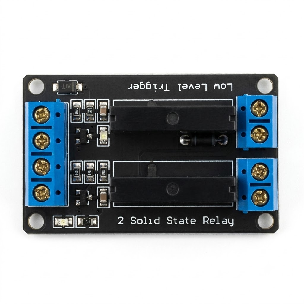 Solid State Relay Module HFS4-2A-05DM SSR with Resistive Fuse 5V, 2-Channel ₹249.00
 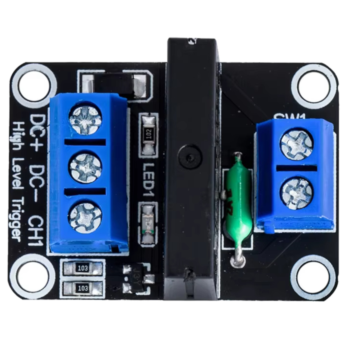 1-Channel 5V Solid-State Relay (SSR) Module - Low-Level Trigger, 250V 2A AC ₹149.00
 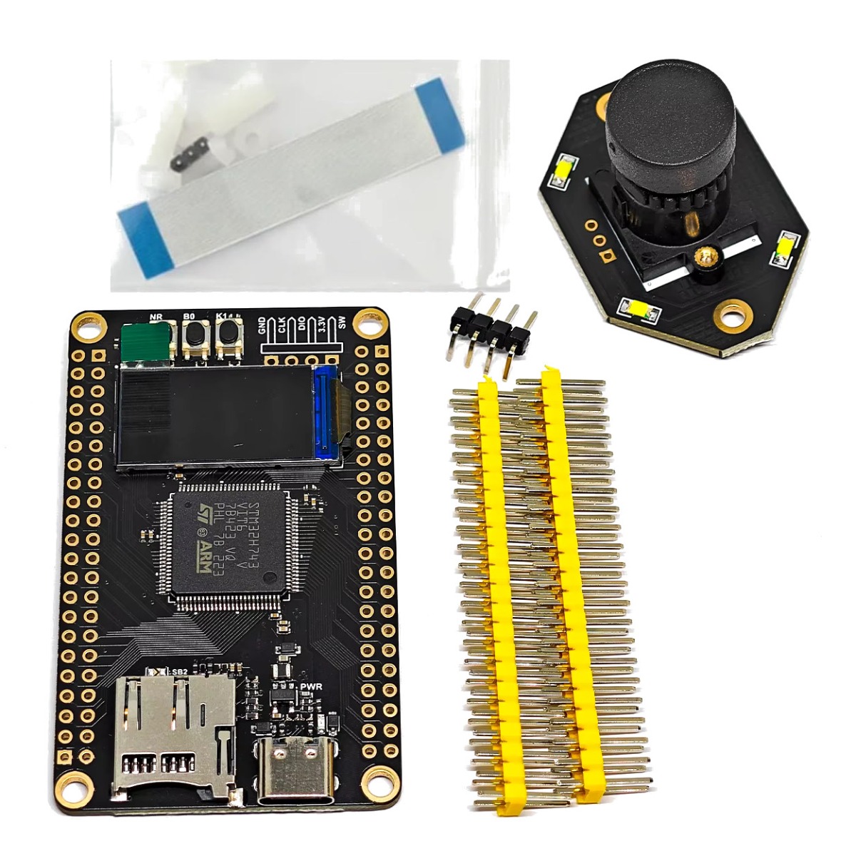 WeAct Studio STM32H743VIT6 Development Core Board With 0.96" TFT Screen OV7725 M12 camera ₹3,999.00
 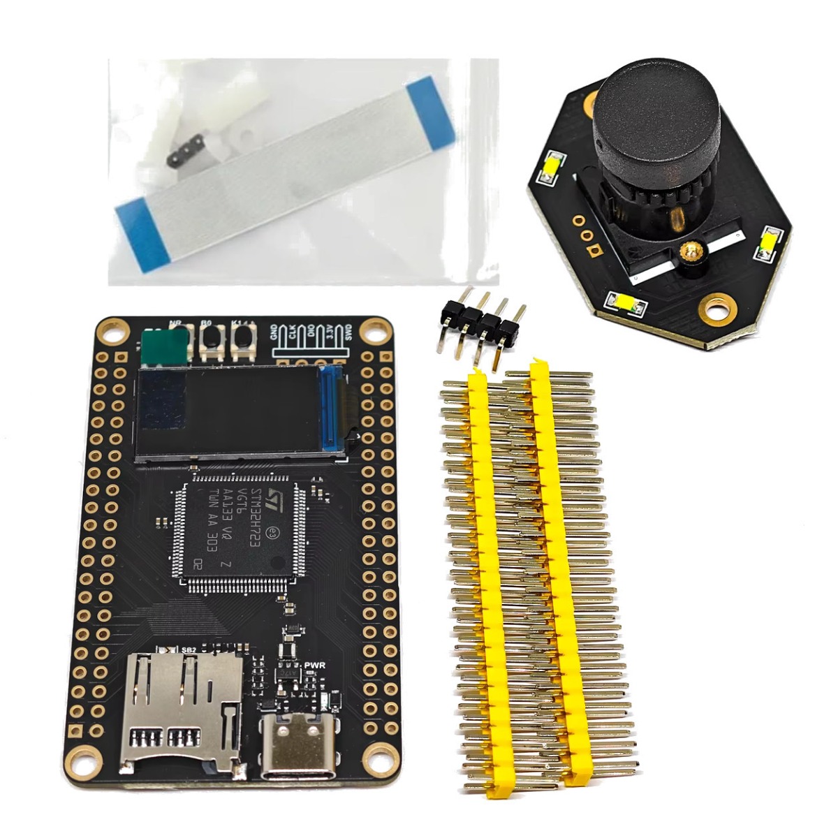 WeAct Studio STM32H723VGT6 Development Core Board With 0.96" TFT Screen OV7725 M12 camera ₹3,899.00
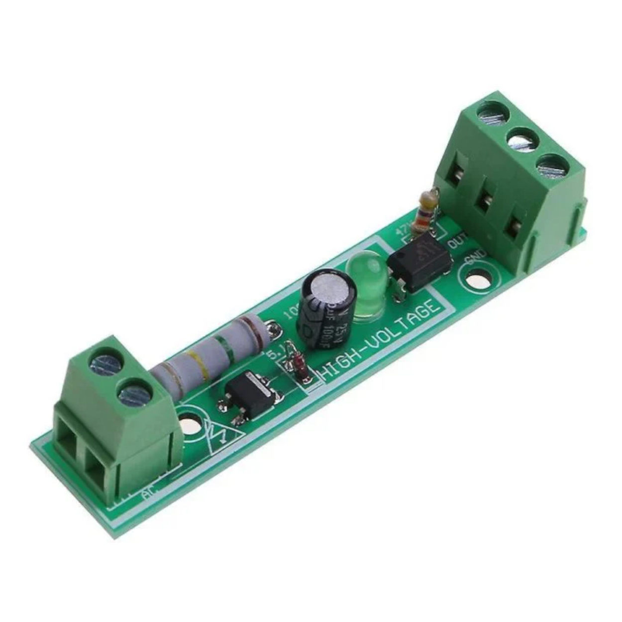
 The Mains Voltage Bridge Sensing whether a high-voltage appliance is turned on, or if the main power grid has failed, is a difficult task. You cannot connect 220V AC directly to an Arduino. This module acts as a safe, optical translator. When 220V AC is applied to the L (Live) and N (Neutral) terminals, the onboard circuitry steps down the voltage to illuminate an internal infrared LED inside the black optocoupler chip. A phototransistor on the safe, low-voltage side of the board sees this light and triggers your output signal. There is absolutely no physical wire connecting the deadly AC side to your fragile DC side.
Wide Logic Compatibility (3V to 24V) Industrial equipment and hobbyist electronics operate on vastly different logic levels. A Raspberry Pi uses 3.3V, an Arduino uses 5V, and an industrial PLC uses 24V. This module supports them all! By supplying your target logic voltage to the VCC and GND pins on the output terminal block, the OUT pin will switch at that exact voltage level, ensuring perfect compatibility with your specific controller.
Active-Low Signal Output It is important to understand how the module communicates. The output signal operates on an "Active-Low" principle.
When 220V AC is OFF: The optocoupler is inactive. The OUT pin is pulled HIGH (it will output whatever voltage you supplied to VCC).
When 220V AC is ON: The optocoupler activates. The OUT pin is pulled LOW (it drops to Ground/0V). Your microcontroller simply monitors this pin for a falling edge.
Safety Warning:
Specifications
Input Voltage: 220V AC (Mains Power)
Output Signal Voltage: 3V to 24V DC
Output Signal Type: Digital (Active-Low)
Isolation Method: Optical (Optocoupler)
Channels: 1 Independent Channel
Connection Interface: Screw Terminal Blocks
Indicator: Onboard green LED for AC power presence
Key Applications and Projects
Smart Home Power Failure Monitor: Connecting the module to the main grid and wiring the output to an ESP32. If the grid fails, the ESP32 (running on a battery backup) instantly senses the pin go HIGH and sends an emergency Telegram or SMS alert to your phone.
Industrial Machine Monitoring: Allowing a modern 24V PLC system to track the run-time and on/off cycles of older 220V legacy motors and pumps.
Appliance State Detection: Detecting if a high-power AC water heater or HVAC system is actively pulling power or has tripped a breaker.
1 x 1-Channel 220V AC Optocoupler Isolation Module
Q: Can this module power my Arduino from the 220V wall outlet? No! This is a sensor, not a power supply. It only detects if 220V is present. You still need a separate, safe DC power supply (like a USB wall wart) to actually power your Arduino.
Q: Is this board safe to touch while operating? Absolutely NOT. The left side of the board (labeled L and N) carries deadly 220V AC mains power. Touching the exposed screw terminals, the large resistor, or the traces on the back of the board while it is plugged in can be fatal. It must be installed inside an insulated, grounded plastic enclosure.
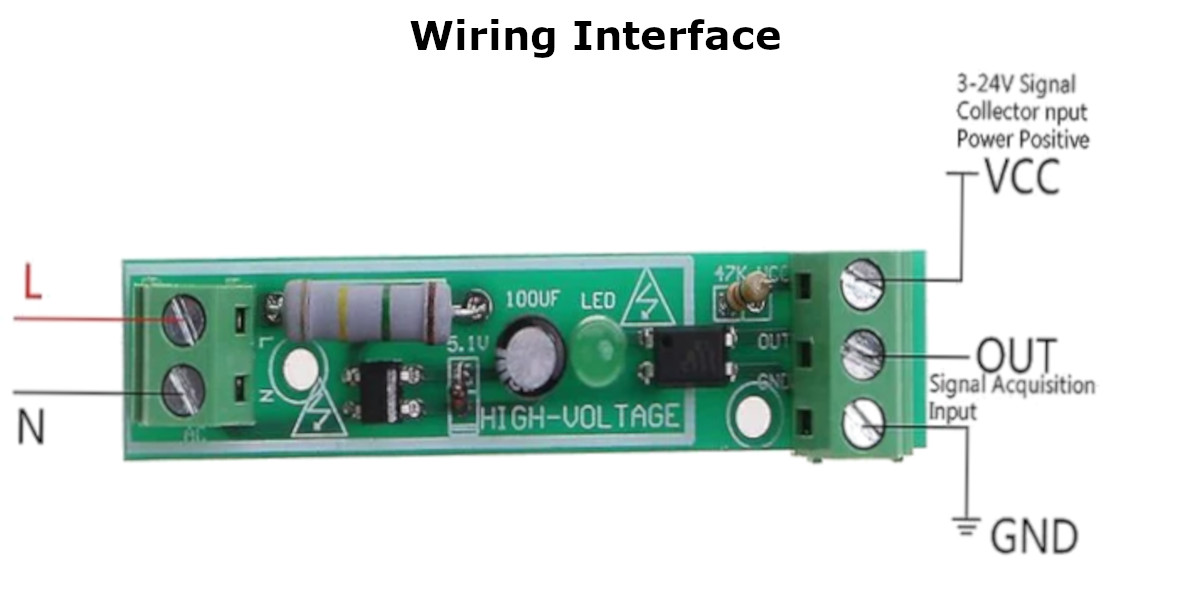
Q: How do I wire the high voltage side? Ensure all power is turned off at the breaker. Wire the Live AC wire to the L terminal and the Neutral AC wire to the N terminal on the green 2-pin block.
Q: How do I wire the low voltage DC side? Wire your microcontroller's positive voltage (e.g., 5V or 3.3V) to the VCC terminal. Wire your microcontroller's Ground to the GND terminal. Finally, connect the OUT terminal to a digital input pin on your microcontroller.
Q: What does the "OUT" pin do when 220V is applied? This is an Active-Low module. When 220V AC is applied, the optocoupler turns on and connects the OUT pin to GND, making your digital pin read LOW (0V).
Q: What does the "OUT" pin do when 220V is turned off? When the AC is turned off, the optocoupler turns off. The onboard pull-up resistor pulls the OUT pin up to whatever voltage you supplied to VCC. Your digital pin will read HIGH.
Q: Will this work with 110V AC (US standard)? These modules are specifically optimized with a large input resistor tuned for 220V-240V AC to prevent overheating. While it may technically trigger on 110V AC, the internal LED will be very dim, and the triggering may be unreliable or erratic. It is best used for 220V systems.
Q: Can I use this to measure the exact AC voltage (like a multimeter)? No. This is a strictly digital, binary sensor. It only outputs an ON or OFF signal. It cannot tell you if the voltage is 210V or 230V, only that the voltage is "present."
Q: Does the module output an analog sine wave? No. The output is a flat, clean DC digital square wave.
Q: What is the purpose of the large grey component on the board? That is a high-wattage power resistor. It drops the massive 220V AC voltage down to a safe level so it doesn't instantly vaporize the tiny LED inside the optocoupler chip.
Q: What does the green LED on the board indicate? The onboard green LED acts as a visual status indicator. It illuminates whenever 220V AC power is actively flowing into the input terminals.
Q: Can I use this with a 24V PLC? Yes. You simply supply 24V DC to the VCC and GND pins. The OUT pin will then output a 24V signal when triggered, which is perfectly readable by standard industrial PLCs.
Q: Can I use this with an ESP8266 or ESP32? Yes. Supply 3.3V from the ESP to the VCC pin. The module will output a safe 3.3V signal to your GPIO pin, ensuring you do not fry the 3.3V-tolerant microcontroller.
Q: Do I need a pull-up resistor on my microcontroller pin? No, you do not need to enable INPUT_PULLUP in your code. The module has its own physical pull-up resistor (often 47K) connected to the VCC pin to keep the OUT line stable when the AC is off.
Q: What is the rectangular black chip in the middle? That is the optocoupler (often a PC817 or similar variant). It bridges the gap between the AC side and the DC side using infrared light, providing the electrical isolation.
Q: Why does my code register multiple rapid ON/OFF triggers when the AC is on? Because AC voltage alternates (crosses zero volts 50 or 60 times a second), cheap modules may rapidly flicker at the zero-crossing point. To fix this, you should write your code to "debounce" the signal, requiring the pin to stay LOW for at least 30-50 milliseconds before confirming the power is actually on. The onboard capacitor helps smooth this, but software debouncing is highly recommended.
Probots sells every Electronics Part for your next Project. You can order 10,000+ Electronic Parts Online - Arduino, Raspberry Pi, NodeMCU Development Boards, Sensors, Motors, Motor Drivers, SMPS, Plastic Enclosures etc in India directly on probots.co.in
We delivery electronics components and parts throughout India using standard couriers like Bluedart, Delhivery & India Post.
For order related queries contact -
This item is covered by a warranty of 7 days from the date of delivery, against confirmed manufacturing defects only, as verified by Probots' own testing and investigation. In case of a confirmed defect, we will replace the item — a refund is issued only if a replacement can't be supplied (e.g. discontinued or out of stock). Transit damage or a wrong item received must be reported within 3 days of delivery.
If the product shows signs of misuse, tampering, physical damage, static discharge, liquid or fire damage, use of unapproved chemicals, or has been soldered or physically altered in any way.
China
Probots sells every Electronics Part for your next Project. You can order 10,000+ Electronic Parts Online - Arduino, Raspberry Pi, NodeMCU Development Boards, Sensors, Motors, Motor Drivers, SMPS, Plastic Enclosures etc in India directly on probots.co.in
We offer specialized services for Bulk, Wholesale & B2B Customers like discounted prices, additional shipping options, customised products, etc . Customer with large quantity & regular orders qualify for the specialised discounted rates.
We also offer dedicated sales team to assist you with the order process by providing sales quotations, PI, technical support for choosing products, etc.
Note: Business Orders are processed manually and usually take 1-3 days to process compared to placing the order directly on our website. Please plan your purchases accordingly.
Need Help?
For bulk enquiries contact us by -


Probots Electronics is highly regarded for its highly skilled team and knowledgeable staff who provide expert guidance to ensure customers select the right components for their technical projects. The business maintains a strong reputation for prompt service and reliable support, with many clients praising their quick response times and genuine commitment to customer satisfaction.


A very great place for electronics Such a well maintained shop... Felt good shopping here


Nice

For new developments kit available and they will support till working, and I suggest this place strongly


This place has all the electronic parts students will ever need, staff is friendly and the place is organised.


It was a really nice experience! I was happy to find such a wide range of robotics kits for kids, suitable for different age groups and learning levels.

Excellent experience




Good stuff

Buyed them. But no bargain. Helpful staff.


Available all children school project spears parts like electronics


It was good experience




Staff is very patient and helpful

One of the best place for electronics you will get everything you want! With the best and orginal quality

Very helpful staff and the best place to buy components for projects

Wonderful store with expert service and technically strong people.

Prompt delivery, excellent technical support


Large inventory of electronic components and parts. Well trained service personnel and technicians who can quickly identify and rectify product defect if any. They are a reliable and trustworthy online stores.

A very great place for electronics Such a well maintained shop... Felt good shopping here
Nice
For new developments kit available and they will support till working, and I suggest this place strongly
This place has all the electronic parts students will ever need, staff is friendly and the place is organised.
It was a really nice experience! I was happy to find such a wide range of robotics kits for kids, suitable for different age groups and learning levels.
Excellent experience
Good stuff
Buyed them. But no bargain. Helpful staff.
Available all children school project spears parts like electronics
It was good experience
Staff is very patient and helpful
One of the best place for electronics you will get everything you want! With the best and orginal quality
Very helpful staff and the best place to buy components for projects
Wonderful store with expert service and technically strong people.
Prompt delivery, excellent technical support
Large inventory of electronic components and parts. Well trained service personnel and technicians who can quickly identify and rectify product defect if any. They are a reliable and trustworthy online stores.
● 20 min readVol. 56 | The Heavyweight DC Drivetrain Duel Reliability isn’t optional when you’re designing actuators that need to move actual steel or
Read Article → ● 13 min read
Workbench Vol. 49 🚀 The Project Trifecta: 3 Builds to Start Today We don’t just stock parts; we curate ecosystems. This week’s arrivals are desi
Read Article → ● 18 min read
Vol. 59 | The Battle of the Bite-Sized Boards Picture a project that needs full Linux, networking, and GPIO—but has almost no room for a conventional
Read Article →