









 ● 20 min read
Showdown: RS550 12V DC 8000 vs RS-555 12V DC 6000 RPM DC Motor
Vol. 56 | The Heavyweight DC Drivetrain Duel Reliability isn’t optional when you’re designing actuators that need to move actual steel or
Read Article →
| Bulk Pricing | ||
|---|---|---|
| QTY | Unit Price(Inlc. GST) | |
| 25+ | ₹122.50 ₹ 103.81 + 18.69 GST | |
| 50+ | ₹121.25 ₹ 102.75 + 18.5 GST | |
| 75+ | ₹120.00 ₹ 101.69 + 18.3 GST | |
| 100+ | ₹117.50 ₹ 99.58 + 17.92 GST | |
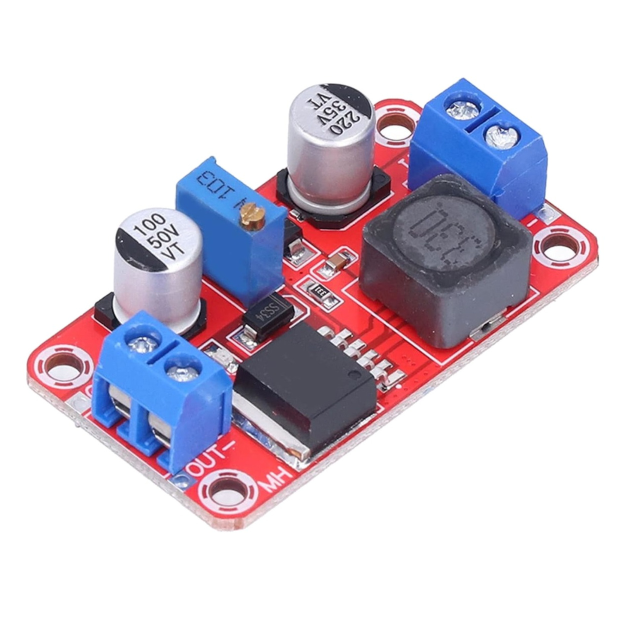
Step up your voltage with precision! The XL6019 module efficiently boosts low input voltages (3V-35V) to higher output voltages (5V-40V). Features reverse-polarity protection and easy-to-use screw terminals.
The XL6019 High-Frequency Advantage For years, the LM2577 was the standard for boosting voltage, but it operated at a slow 52KHz, which often resulted in audible "coil whine" and required massive capacitors to smooth out the ripple. The XL6019 is a next-generation upgrade. It operates at 220KHz. This higher switching frequency means the module can react to sudden load changes much faster, produces a significantly cleaner DC output with less voltage ripple, and runs silently.
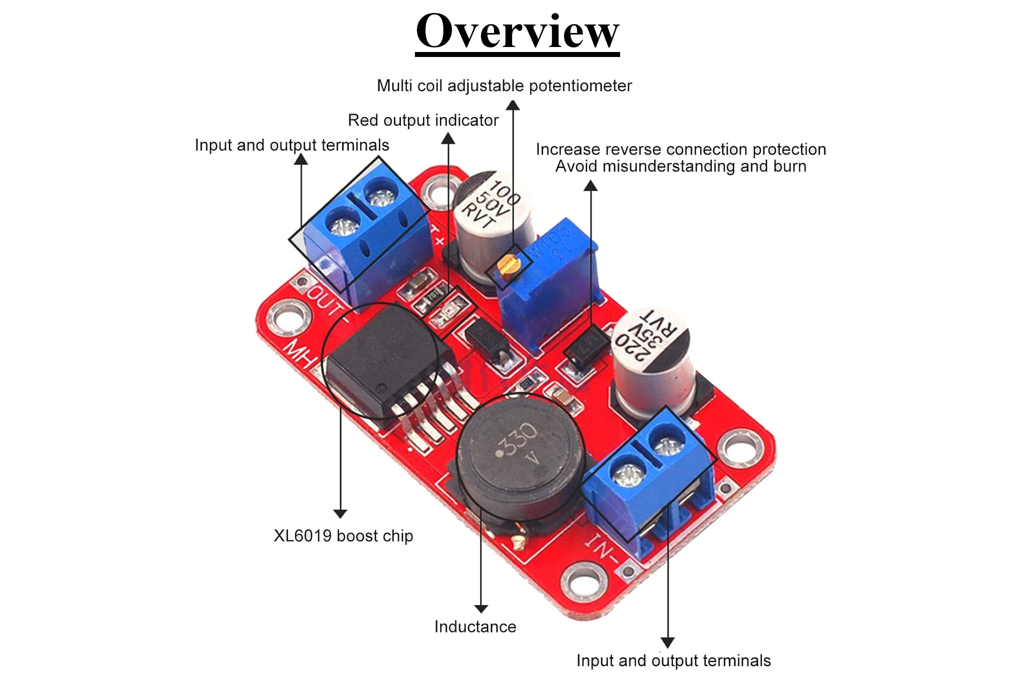
Addressing the Buck-Boost Misconception It is important to understand your hardware. While generic titles often label this as an "Auto Boost Buck Step Down" module, the physical trace routing, the single 330µH inductor, and the "DC-DC STEP-UP" label printed on the bottom of the PCB dictate that this is a standard Boost Converter. Your input voltage must always be lower than your desired output voltage. If you supply 12V to the input, the module cannot output 5V. It is designed to take a lower voltage (like a 3.7V lithium battery) and boost it up to a higher voltage (like 12V to run an LED strip).
Integrated Safety Features Working with prototype power supplies can be risky. This module features an integrated M7 diode near the input terminals, providing crucial reverse-connection protection. If you accidentally wire your battery backward, this diode prevents the XL6019 chip from instantly exploding, giving you a chance to correct your wiring.
Specifications
Regulator IC: XL6019
Module Type: Non-isolated Step-Up (Boost)
Input Voltage Range: 3.0V to 35V DC
Output Voltage Range: 5.0V to 40V DC (Adjustable)
Maximum Switching Current: 5A (Internal switch limit)
Continuous Output Current: ~1.5A to 3A (Depends heavily on input/output voltage differential and cooling)
Switching Frequency: 220 KHz
Conversion Efficiency: Up to 94%
Potentiometer Type: 10K Multi-Turn (W103)
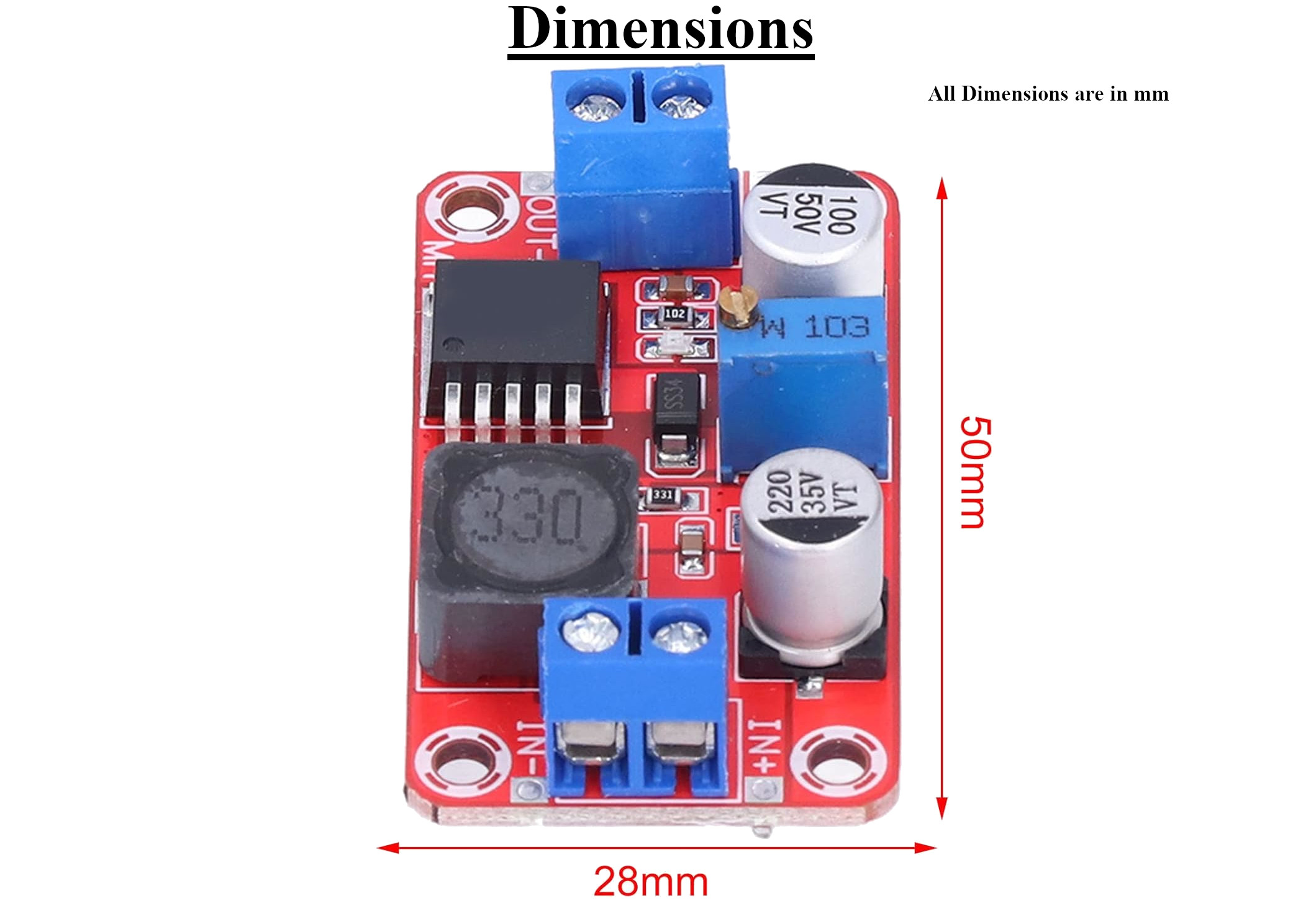
Dimensions: 50mm (L) x 28mm (W) x 13mm (H)
Reverse Polarity Protection: Yes (via input diode)
Key Applications and Projects
Portable Audio Amplifiers: Boosting a 3.7V Li-ion battery pack up to 12V or 24V to power a high-wattage Class-D audio amplifier board in a custom Bluetooth speaker.
12V Automotive Integration: Stepping up a fluctuating 12V car battery system to a perfectly stable 19V or 24V to run specialized networking equipment or laptops in a mobile workbench.
Solar Power Harvesting: Taking the variable 5V to 9V output of a small solar panel and boosting it to a consistent voltage required to run a 12V water pump for automated greenhouse irrigation.
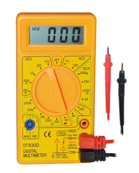
Unlock New Capabilities (Project Evolution) The Ultimate 5V USB to 12V Adapter: Do you have a 12V router, LED strip, or fan, but only have a standard 5V USB power bank during a power outage? Evolve your emergency kit! Cut an old USB cable and wire the red and black power lines into the IN+ and IN- terminals of the XL6019. Connect your multimeter to the output and turn the blue potentiometer until the output reads exactly 12V. You have just created a highly efficient, custom USB-to-12V step-up cable capable of running networking gear for hours off a standard cell phone power bank!
1 x XL6019 5A DC-DC Boost Converter Module
1. What does this module do? It is a DC-to-DC Boost Converter. It takes a lower direct current (DC) voltage from a power source (like a battery) and increases (boosts) it to a higher, stable DC voltage.
2. The title says "Buck Step Down", can this lower my voltage? No. Despite the generic, often confusing factory title, the physical architecture of this specific board is a Step-Up (Boost) converter. The input voltage must always be lower than the desired output voltage. If you need to lower voltage, you need an LM2596 "Buck" converter.
3. What is the maximum current it can handle? The XL6019 chip has a 5A internal switching limit. However, the actual continuous output current you can draw depends on how hard the chip is working. Typically, you can draw 1.5A to 3A continuously before the chip requires an external heatsink.
4. How do I adjust the output voltage? Attach a multimeter to the OUT+ and OUT- terminals. Use a small flathead screwdriver to turn the brass screw on the blue W103 potentiometer. Turn counter-clockwise to increase voltage, and clockwise to decrease it.
5. Why is the output voltage not changing when I turn the screw? Multi-turn potentiometers have a very fine adjustment resolution. You may need to spin the tiny screw 10, 15, or even 20 full rotations before the internal wiper engages the resistive track and begins changing the voltage. Keep turning!
6. Does it have reverse polarity protection? Yes. The board features an M7 diode specifically added to provide reverse connection protection, preventing catastrophic damage if you mix up the positive and negative input wires.
7. Can I use this to step up 5V to 12V? Absolutely. Stepping up 5V USB or 5V logic power to 12V for fans or relays is one of the most common applications for this module.
8. What is the minimum input voltage required? The chip requires a minimum of 3.0V to power its internal oscillator and logic circuitry reliably.
9. Can I use this to charge a lithium battery? It is highly discouraged. This is a Constant Voltage (CV) power supply. Charging raw lithium batteries requires a specialized Constant Current / Constant Voltage (CC/CV) charging module to prevent fires.
10. What are the blue blocks on the ends? These are screw terminal blocks. You insert your stripped wires into the holes and tighten the top screws to secure them, eliminating the need to solder wires directly to the board.
11. Is the output voltage isolated from the input? No. This is a non-isolated converter. The IN- and OUT- (Ground) terminals share a common electrical connection across the board.
12. What does "220KHz Switching Frequency" mean for my project? It means the chip turns the inductor on and off 220,000 times a second. This high frequency allows for a very stable output voltage with minimal ripple (electrical noise), making it excellent for sensitive audio or radio equipment.
13. Does this module need a heatsink? If you are drawing less than 15 Watts of total power (e.g., boosting 5V to 12V at 1 Amp), it will run cool. If you are pushing the module past 20 Watts, you should attach a small adhesive aluminum heatsink to the black XL6019 chip.
14. What are the dimensions of the board? The PCB measures 50mm long, 28mm wide, and stands approximately 13mm tall (at the highest capacitor).
15. Can I run a 100W laptop charger off this? No. 100 Watts would far exceed the 5A internal switching limit and thermal capacity of this small module. You would need a much larger, 150W or 300W heavy-duty boost converter for a laptop.
16. Why is my module making a high-pitched whining noise? The XL6019 operates at 220KHz, which is far beyond human hearing. If you hear whining, it means the inductor is vibrating due to "sub-harmonic oscillation." This usually happens if your input power supply is too weak and the voltage is collapsing under load.
17. Do I need to add external capacitors? No, the board is fully populated. It features a 220µF 35V capacitor on the input side and a 100µF 50V capacitor on the output side to filter the voltage automatically.
18. What happens if my input voltage fluctuates (like from a solar panel)? As long as the input voltage remains below your set output voltage, the XL6019 will actively compensate and keep the output voltage perfectly stable.
19. How efficient is this converter? Under optimal conditions (a small difference between input and output voltage), it operates at up to 94% efficiency. However, if you are boosting a very low voltage to a very high voltage (e.g., 3V to 30V), efficiency will drop, and more power will be lost as heat.
20. Can I connect two of these in parallel to get 10 Amps? No! Switching power supplies cannot be wired in parallel. Microscopic differences in their output voltages will cause them to fight each other, resulting in severe overheating and module failure.
Probots sells every Electronics Part for your next Project. You can order 10,000+ Electronic Parts Online - Arduino, Raspberry Pi, NodeMCU Development Boards, Sensors, Motors, Motor Drivers, SMPS, Plastic Enclosures etc in India directly on probots.co.in
We delivery electronics components and parts throughout India using standard couriers like Bluedart, Delhivery & India Post.
For order related queries contact -
This item is covered by a warranty of 7 days from the date of delivery, against confirmed manufacturing defects only, as verified by Probots' own testing and investigation. In case of a confirmed defect, we will replace the item — a refund is issued only if a replacement can't be supplied (e.g. discontinued or out of stock). Transit damage or a wrong item received must be reported within 3 days of delivery.
If the product shows signs of misuse, tampering, physical damage, static discharge, liquid or fire damage, use of unapproved chemicals, or has been soldered or physically altered in any way.
China
Probots sells every Electronics Part for your next Project. You can order 10,000+ Electronic Parts Online - Arduino, Raspberry Pi, NodeMCU Development Boards, Sensors, Motors, Motor Drivers, SMPS, Plastic Enclosures etc in India directly on probots.co.in
We offer specialized services for Bulk, Wholesale & B2B Customers like discounted prices, additional shipping options, customised products, etc . Customer with large quantity & regular orders qualify for the specialised discounted rates.
We also offer dedicated sales team to assist you with the order process by providing sales quotations, PI, technical support for choosing products, etc.
Note: Business Orders are processed manually and usually take 1-3 days to process compared to placing the order directly on our website. Please plan your purchases accordingly.
Need Help?
For bulk enquiries contact us by -

Probots Electronics is highly regarded for its highly skilled team and knowledgeable staff who provide expert guidance to ensure customers select the right components for their technical projects. The business maintains a strong reputation for prompt service and reliable support, with many clients praising their quick response times and genuine commitment to customer satisfaction.


A very great place for electronics Such a well maintained shop... Felt good shopping here


Nice

For new developments kit available and they will support till working, and I suggest this place strongly


This place has all the electronic parts students will ever need, staff is friendly and the place is organised.


It was a really nice experience! I was happy to find such a wide range of robotics kits for kids, suitable for different age groups and learning levels.

Excellent experience




Good stuff

Buyed them. But no bargain. Helpful staff.


Available all children school project spears parts like electronics


It was good experience




Staff is very patient and helpful

One of the best place for electronics you will get everything you want! With the best and orginal quality

Very helpful staff and the best place to buy components for projects

Wonderful store with expert service and technically strong people.

Prompt delivery, excellent technical support


Large inventory of electronic components and parts. Well trained service personnel and technicians who can quickly identify and rectify product defect if any. They are a reliable and trustworthy online stores.

A very great place for electronics Such a well maintained shop... Felt good shopping here
Nice
For new developments kit available and they will support till working, and I suggest this place strongly
This place has all the electronic parts students will ever need, staff is friendly and the place is organised.
It was a really nice experience! I was happy to find such a wide range of robotics kits for kids, suitable for different age groups and learning levels.
Excellent experience
Good stuff
Buyed them. But no bargain. Helpful staff.
Available all children school project spears parts like electronics
It was good experience
Staff is very patient and helpful
One of the best place for electronics you will get everything you want! With the best and orginal quality
Very helpful staff and the best place to buy components for projects
Wonderful store with expert service and technically strong people.
Prompt delivery, excellent technical support
Large inventory of electronic components and parts. Well trained service personnel and technicians who can quickly identify and rectify product defect if any. They are a reliable and trustworthy online stores.
● 20 min readVol. 56 | The Heavyweight DC Drivetrain Duel Reliability isn’t optional when you’re designing actuators that need to move actual steel or
Read Article →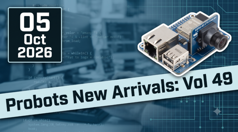 ● 13 min read
Workbench Vol. 49 🚀 The Project Trifecta: 3 Builds to Start Today We don’t just stock parts; we curate ecosystems. This week’s arrivals are desi
Read Article →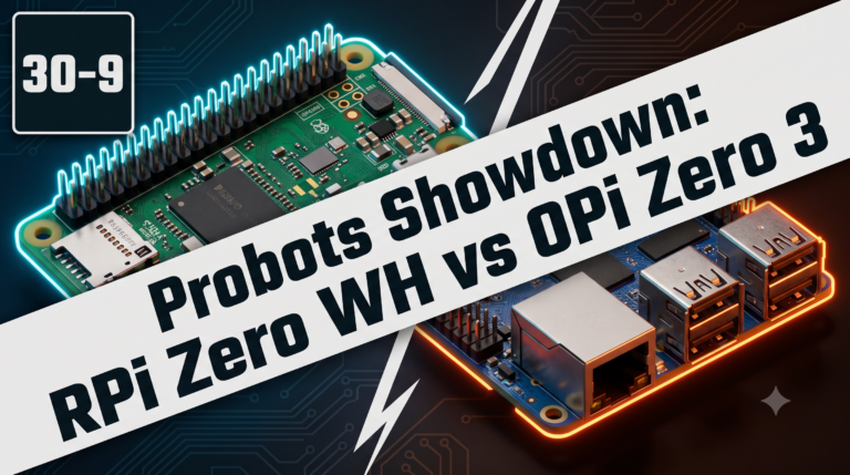 ● 18 min read
Vol. 59 | The Battle of the Bite-Sized Boards Picture a project that needs full Linux, networking, and GPIO—but has almost no room for a conventional
Read Article →