














 ● 20 min read
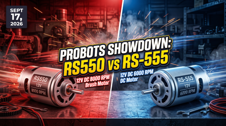
Showdown: RS550 12V DC 8000 vs RS-555 12V DC 6000 RPM DC Motor
Vol. 56 | The Heavyweight DC Drivetrain Duel Reliability isn’t optional when you’re designing actuators that need to move actual steel or
Read Article →
| Bulk Pricing | ||
|---|---|---|
| QTY | Unit Price(Inlc. GST) | |
| 25+ | ₹223.44 ₹ 189.36 + 34.08 GST | |
| 50+ | ₹221.16 ₹ 187.42 + 33.74 GST | |
| 75+ | ₹218.88 ₹ 185.49 + 33.39 GST | |
| 100+ | ₹214.32 ₹ 181.63 + 32.69 GST | |
Accurately read tiny sensor signals! This module uses the AD620A chip to amplify microvolt/millivolt inputs. It operates on a 3~10VDC supply and features onboard zero calibration and adjustable gain.
High-Precision Instrumentation At the center of this module is the AD620A integrated circuit. As a true instrumentation amplifier, it is specifically designed to measure the voltage difference between two input signals (S+ and S-) while rejecting any noise common to both wires (High Common-Mode Rejection Ratio). This makes it the absolute perfect choice for reading the tiny differential voltage changes produced by Wheatstone bridge sensors, such as load cells or pressure transducers.
Single-Supply Convenience Standard operational amplifiers often require a complex dual power supply (+V and -V) to amplify signals that swing near or below ground. This module simplifies your wiring drastically! By incorporating an HT7660 (or equivalent 7660) charge pump voltage converter chip, the board automatically generates a negative voltage internally. This means you only need to supply a standard 3 to 10VDC power source to the VIN and GND pins. The board even breaks out this generated negative voltage on the V- (Negative Pressure) output pin for your convenience.
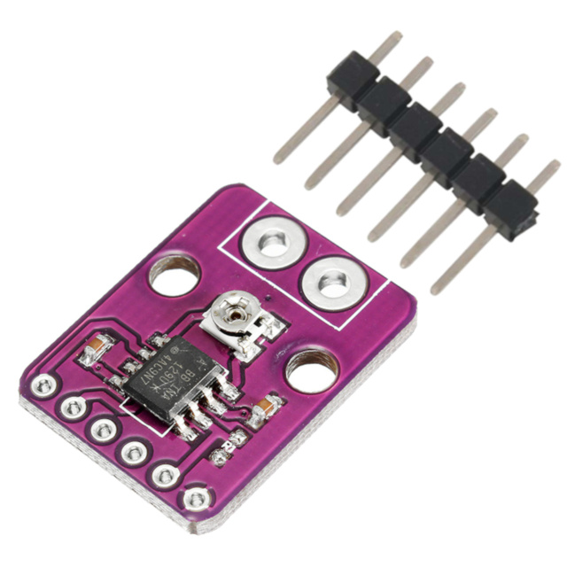
Hardware Tuning at Your Fingertips To ensure your analog readings are perfectly mapped to your microcontroller's ADC, the board features two blue 3296 trim potentiometers.
Zero Calibration: The top potentiometer is used to calibrate the zero point. Assisted by the onboard LM358 op-amp, this allows you to completely eliminate any baseline DC offset from your sensor before amplification.
Adjustable Gain: The bottom potentiometer is used to adjust the magnification (gain) of the signal. By turning this screw, you can dynamically scale your tiny input signal up to a robust voltage that is easily readable by a 3.3V or 5V logic board.
Specifications
Main Amplifier Chip: AD620A
Voltage Converter Chip: HT7660
Offset Op-Amp: LM358
Power Supply (VIN): 3~10VDC
Signal Inputs: S+ (Positive), S- (Negative)
Outputs: Vout (Amplified Signal), V- (Negative Voltage Reference)
Tuning: 2x 3296 Potentiometers (Gain and Zero Offset)
Dimensions: 32mm (Length) x 22mm (Width)
Downloads:
Key Applications and Projects
Digital Scales: Amplifying the weak differential output from a strain gauge load cell so an Arduino can accurately calculate weight.
Biomedical Sensors: Building DIY ECG (Electrocardiogram) or EMG (Electromyogram) circuits to read tiny electrical impulses from muscles or the heart.
Industrial Sensor Interfacing: Boosting signals from long cable runs or low-output thermocouples to prevent signal degradation before reaching the main control board.
Unlock New Capabilities (Project Evolution) The Custom Smart Scale: Move beyond basic blinking LEDs and build a practical measurement tool! Wire a 5kg aluminum load cell to the S+ and S- inputs of this module. Supply the board with 5V from an Arduino Uno. Use a multimeter to adjust the top calibration potentiometer until Vout reads exactly 0V with no weight on the scale. Place a known weight on the scale, and adjust the bottom magnification potentiometer until you get a strong, readable voltage. Feed Vout into the Arduino's analog pin, add a simple OLED screen, and you have built a highly accurate, custom digital scale from scratch!
1 x AD620 Voltage Amplifier Module
2 x 4-Pin Male Headers (Unsoldered)

1. What is the main purpose of this module? It is designed to take extremely weak electrical signals (microvolts or millivolts) from sensors and amplify them into a larger voltage range that a standard microcontroller can easily read.
2. What is the input power requirement? The module requires a DC power supply between 3V and 10V connected to the positive and negative power supply pins.
3. What does the HT7660 chip do? The HT7660 is a charge pump voltage converter. It takes your positive input voltage and flips it to generate a negative voltage rail internally, which is required for the AD620 to operate properly around a zero-volt baseline.
4. What is the V- pin on the output side used for? This is the Negative Pressure (-Vin) output. It provides access to the negative voltage generated by the HT7660 chip, which you can use as a reference or to power other dual-supply op-amps in your project.
5. What is the difference between S+ and S-? These are the differential signal inputs. The AD620 amplifier measures the difference in voltage between the S+ and S- pins, rather than measuring a single pin against ground.
6. How do I adjust the amplification (gain)? You adjust the magnification (gain) by turning the brass screw on the top blue potentiometer.
7. How do I remove the baseline offset (Zero Calibration)? You can calibrate the zero offset by turning the bottom blue potentiometer. Short the S+ and S- pins together to simulate a zero-input state, measure the Signal Output (Vout) pin with a multimeter, and slowly adjust this potentiometer until the output voltage reads exactly 0.00V.
8. What is the LM358 chip used for? The LM358 dual operational amplifier works in conjunction with the calibration potentiometer to buffer and inject the zero-calibration offset voltage into the AD620's reference pin.
9. Are the header pins pre-soldered? No, the module includes two loose 4-pin male headers. You will need a soldering iron to attach them to the board.
10. What are the physical dimensions of the board? The printed circuit board measures 32mm in length and 22mm in width.
11. Can I use this with a 3.3V microcontroller like an ESP32? Yes. You can supply 3.3V to the power supply pins. Just ensure that you tune the magnification potentiometer so that the maximum Vout signal does not exceed your microcontroller's 3.3V analog input limit.
12. Why do the potentiometers say "3296"? "3296" is the standard component code for this specific style of multi-turn precision trim potentiometer, as printed on the side of the blue housing.
13. Does this module work with load cells? Yes, it is exceptionally well-suited for load cells. A load cell is a Wheatstone bridge that outputs a differential millivolt signal, which connects perfectly to the S+ and S- signal inputs.
14. What do the exposed silver pads on the bottom do? The bottom of the board shows the through-hole solder joints for the two 3296 potentiometers.
15. Is this board suitable for high-frequency AC signals? Instrumentation amplifiers like the AD620 are generally optimized for DC or relatively low-frequency AC signals (like biological data or mechanical strain). They are not designed for high-frequency RF or fast audio amplification.
16. Which specific instrumentation amplifier chip is used? The board utilizes the AD620A chip for high-precision signal amplification.
17. How many connection pins are located on the input side (J1)? The input side, labeled J1, features four connection pins: Power Supply +, Power Supply -, Signal Input S-, and Signal Input S+.
18. How many connection pins are located on the output side (J3)? The output side, labeled J3, features four connection pins: Negative Pressure Output (V-), GND, Signal Output (Vout), and GND.
19. Can I power this module with a 12V supply? No, it is not recommended. The maximum rated input for the power supply is 10VDC. Supplying 12V may damage the onboard components.
20. What is the purpose of the four holes in the corners of the PCB? These are structural mounting holes that allow you to securely screw or mount the module inside a custom enclosure or onto a chassis.

Probots sells every Electronics Part for your next Project. You can order 10,000+ Electronic Parts Online - Arduino, Raspberry Pi, NodeMCU Development Boards, Sensors, Motors, Motor Drivers, SMPS, Plastic Enclosures etc in India directly on probots.co.in
We delivery electronics components and parts throughout India using standard couriers like Bluedart, Delhivery & India Post.
For order related queries contact -
This item is covered by a warranty of 7 days from the date of delivery, against confirmed manufacturing defects only, as verified by Probots' own testing and investigation. In case of a confirmed defect, we will replace the item — a refund is issued only if a replacement can't be supplied (e.g. discontinued or out of stock). Transit damage or a wrong item received must be reported within 3 days of delivery.
If the product shows signs of misuse, tampering, physical damage, static discharge, liquid or fire damage, use of unapproved chemicals, or has been soldered or physically altered in any way.
China
Probots sells every Electronics Part for your next Project. You can order 10,000+ Electronic Parts Online - Arduino, Raspberry Pi, NodeMCU Development Boards, Sensors, Motors, Motor Drivers, SMPS, Plastic Enclosures etc in India directly on probots.co.in
We offer specialized services for Bulk, Wholesale & B2B Customers like discounted prices, additional shipping options, customised products, etc . Customer with large quantity & regular orders qualify for the specialised discounted rates.
We also offer dedicated sales team to assist you with the order process by providing sales quotations, PI, technical support for choosing products, etc.
Note: Business Orders are processed manually and usually take 1-3 days to process compared to placing the order directly on our website. Please plan your purchases accordingly.
Need Help?
For bulk enquiries contact us by -

Probots Electronics is highly regarded for its highly skilled team and knowledgeable staff who provide expert guidance to ensure customers select the right components for their technical projects. The business maintains a strong reputation for prompt service and reliable support, with many clients praising their quick response times and genuine commitment to customer satisfaction.


A very great place for electronics Such a well maintained shop... Felt good shopping here


Nice

For new developments kit available and they will support till working, and I suggest this place strongly


This place has all the electronic parts students will ever need, staff is friendly and the place is organised.


It was a really nice experience! I was happy to find such a wide range of robotics kits for kids, suitable for different age groups and learning levels.

Excellent experience




Good stuff

Buyed them. But no bargain. Helpful staff.


Available all children school project spears parts like electronics


It was good experience




Staff is very patient and helpful

One of the best place for electronics you will get everything you want! With the best and orginal quality

Very helpful staff and the best place to buy components for projects

Wonderful store with expert service and technically strong people.

Prompt delivery, excellent technical support


Large inventory of electronic components and parts. Well trained service personnel and technicians who can quickly identify and rectify product defect if any. They are a reliable and trustworthy online stores.

A very great place for electronics Such a well maintained shop... Felt good shopping here
Nice
For new developments kit available and they will support till working, and I suggest this place strongly
This place has all the electronic parts students will ever need, staff is friendly and the place is organised.
It was a really nice experience! I was happy to find such a wide range of robotics kits for kids, suitable for different age groups and learning levels.
Excellent experience
Good stuff
Buyed them. But no bargain. Helpful staff.
Available all children school project spears parts like electronics
It was good experience
Staff is very patient and helpful
One of the best place for electronics you will get everything you want! With the best and orginal quality
Very helpful staff and the best place to buy components for projects
Wonderful store with expert service and technically strong people.
Prompt delivery, excellent technical support
Large inventory of electronic components and parts. Well trained service personnel and technicians who can quickly identify and rectify product defect if any. They are a reliable and trustworthy online stores.
● 20 min readVol. 56 | The Heavyweight DC Drivetrain Duel Reliability isn’t optional when you’re designing actuators that need to move actual steel or
Read Article → ● 13 min read
Workbench Vol. 49 🚀 The Project Trifecta: 3 Builds to Start Today We don’t just stock parts; we curate ecosystems. This week’s arrivals are desi
Read Article →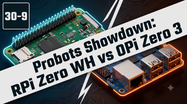 ● 18 min read
Vol. 59 | The Battle of the Bite-Sized Boards Picture a project that needs full Linux, networking, and GPIO—but has almost no room for a conventional
Read Article →